
Introduction
I have seen quite a few schematics lately that are using an operational amplifier (opamp) configured as a negative resistor. I thought it would be interesting to analyze this circuit and show how it can provide an economical solution to a common sensor interface scenario.
Background
Figure 1 illustrates a common sensor interface scenario. This scenario consists of:
- Sensor
The sensor has a resistance characteristic that varies according to some external parameter, e.g. temperature, ambient light level, gas concentration. - Current Source
A current source drive can be desirable for a number of reasons: (1) The sensor may be calibrated for a specific current level, (2) The sensor may have a linear response for a given current drive, (3) The sensor output voltage range needs to be restricted in some way. - Amplifier
The amplifier is often needed to provide isolation from the monitoring circuitry and to scale the output for further signal processing.

Figure 1: Common Sensor Interface Scenario.
Negative Resistance Opamp Circuit
Figure 2 shows an operational amplifier connected as a negative resistance.

Figure 2: Negative Resistance Circuit.
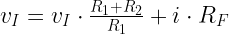
Equation 1 shows the derivation of the negative resistance equation.
| Eq. 1 | 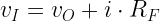 |
 |
|
 |
|
 |
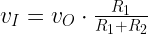
Equation 2 shows the derivation of the voltage gain equation.
| Eq. 2 |  |
Introduction
My application example is shown in Figure 4.

Figure 3: Negative Resistance Example Application.
The basic idea here is to use negative input resistance of the opamp circuit to cancel out the resistance of RS. Figure 4 illustrates this source transformation.

Figure 4: Source Transformation.
The parameters of this case are the following:


Figure 4 shows my solution in Mathcad.

Figure 5: Example Solution in Mathcad.
Conclusion
I worked through some basic design equations for the application of a negative resistance circuit to a sensor interface example. I have been seeing this circuit quite a bit lately and it is an interesting application of basic linear circuit analysis.