
Quote of the Day
Nobody washes a rental car.
— Truism on the importance of ownership and maintenance
Introduction

Figure 1: Example of a crimped connection using a commonly available connector. Many mechanical engineers love crimped connections because they can be hermetic. However, they require the correct tool to be properly executed. (Source)
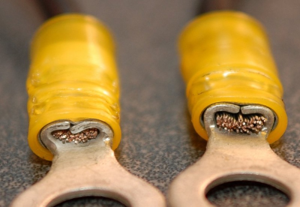
I have written dozens (hundreds?) of small Mathcad function to help me in my daily work. Since I plan to teach another Mathcad class soon, I am gathering examples that might be good to use as application examples. Yesterday, I was working with a customer on selecting wires for supplying power to our products. I used an old calculator that I have decided to show my students in the class. I will discuss how I used this calculator here.
These wires need to be joined (i.e. spliced). The customer wanted to use crimp connectors for this joining process rather than soldering. Crimping wire connections is preferred by many engineers because:
- simpler
There are numerous hand tools that allow you to simply put the wires together and join with by simply squeezing the tools handle.
- safe
Soldering can involve heavy metals and nasty fluxes.
- reliable
When performed by the proper tool, crimp joints can be very reliable.
This particular customer wanted to use this brand of connectors. There are rules on which connectors must be selected for a given area of copper. It turns out that I have a Mathcad worksheet that helps me to quickly select the specific connector for the given wires being used.
Background
Wires are pretty straightforward, but the units of measure (in the US) are rather strange. The following Wikipedia reference will provide the proper background to understand this calculator.
Analysis
Figure 1 shows the basic setup used to define the characteristics of both the wire gauges and the connectors.

Figure 1: Mathcad Worksheet Section that Defines the Wire Types and Connectors.
Figure 2 shows the user input section of the worksheet. I use some simple control ("text boxes") to accept user input. I also have a small program that searches for the connector size that matches my needs. The calculator assumes that multiple wires of two different gauges are being joined.

Figure 2: Mathcad Worksheet User Input and Computation Section.
Conclusion
This blog just reviews a routine wire area and connector calculator. I use this calculator so often that I do not even think about it.
You can get a copy of the calculator here. It is in Mathcad 15.
This is pretty awesome. I am not a maths person, but I am looking into a formula for calculating the height of a crimp for a specified wire gauge. For example, I have a 17 gauge wire and a 16 gauge wire that need to be connected with a splice crimp instead of soldering.
as I understand it, ((CMIL+9360)/190400) should work for one connector, ((cmil+14,600)/243900) for the next, and ((cmil+23000)/312500)should work for the last connector in the arsenal.
is this something that mathCAD Express might be able to handle? I just downloaded the trial.