Derivation of the Output Power Equation
The output power equation (Equation 3) is really a restatement of Newton's law of cooling. Equation 3 states the battery's steady-state power dissipation is a linear function of the battery's temperature and the ambient temperature. This equation assumes that the power generated within the enclosure is dissipated by convection and conduction, which is a good assumption at low battery temperatures.
| Eq. 3 |
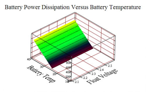
Figure 6 shows a graph of this equation assuming that GThermal = 50 mW/°C and TAmbient = 25 °C (I measured this characteristic on a small battery in my lab).
Values for GThermal will vary for each battery design and state (e.g. age, charge history). For example, the large battery used in the example below from the reference paper has GThermal = 690 mW/°C.
Analysis
Thermal Runaway Operating Conditions
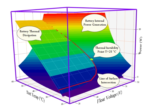
Figure 7 shows a combined plot of PIN and POUT. The point of intersection of these two curves (marked by a pink line) is where , which means that the battery temperature and float voltage are stable at that power level. When PIN exceeds POUT, the temperature of the battery will begin to increase. Under typical operating conditions, the battery will simply stabilize at a higher temperature that allows the internal power to be dissipated. However, battery temperature can only go so high before the electrolyte boils away, resulting in the destruction of the battery. If the battery operating point is such that PIN always exceeds POUT prior to reaching the destructive temperature, the battery will destroy itself. This is not good.
Figure 7 is based on my estimate of the parameters for a battery (Y3) from the original paper. Here are the coefficients I used:
- GTherm=0.690 W/°C
- float current:
- k = -25.939187
- β = 0.096457 1/°C
- α = 0.909478 1/V
- battery power:
In Figure 7, I actually plotted Watts instead of milliWatts.
Condition for Thermal Runaway
We can derive a criticality condition for thermal runaway by observing that (1) PIN = POUT and (2) the slopes of the two curves must be equal at their points of intersection (see Equations 4 and 5, respectively).
| Eq. 4 | |
| |
| Eq. 5 | |
| |
If we make a ratio of these two equations, simplify, and solve for TBattery, we obtain Equation 6.
| Eq. 6 |
We can substitute the constraint of Equation 6 back into Equation 4. After a bit of algebraic manipulation, I get Equation 7. Note that my Equation 7 is different than that of the paper I am reviewing. I have done all sorts of verification and I believe that my version is correct.
| Eq. 7 |
Let's examine Equation 7 just a bit.
- Higher ambient temperature lowers the maximum allowed charging voltage.
This makes complete sense to me. My experience is that batteries operating under high ambient temperatures are more subject to thermal runaway. - Improved battery cooling (i.e. lower β) makes thermal runaway less likely.
Again, I have rarely seen thermal runaway when the battery has a good thermal design. For example, batteries in a flat package generally have better thermal conductivity and appear to me to be less likely to runaway. - Old batteries are more likely to thermally runaway than new batteries.
Old batteries require higher charging currents (i.e. higher α) and have lower thermal conductivity (i.e. GThermal is smaller), each of which reduce the critical voltage level.
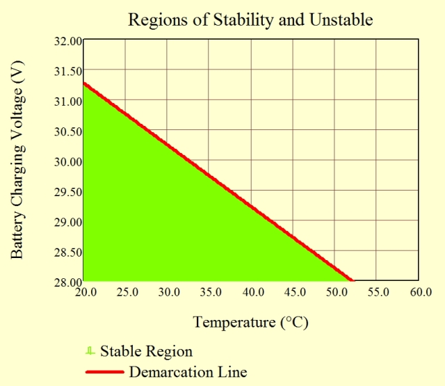
Figure 8 is a graph of Equation 7. You will see that the demarcation line between thermally stable and unstable regions is nearly linear. As the reference paper shows, this linearity can be explained by a slight rearrangement of Equation 7 into Equation 8.
| Eq. 8 | 
|
The function is roughly constant over a limited voltage region because of the logarithmic dependence of the right-hand side of Equation 8 on VMax. This means that the function appears to be nearly linear when plotted on a graph.
Figure 8 clearly shows that a combination of high charging current and high ambient temperature makes thermal runaway more likely.
Conclusion
My objective was to duplicate the analysis details discussed the paper I am reviewing here. The paper derived results that I have observed in my work with batteries, which I summarize below.
- Higher ambient temperature makes thermal runaway more likely.
- Higher charging voltage makes thermal runaway more likely.
- Some batteries are more susceptible than others (e.g. old batteries and those with poor thermal design).


Hi. Excellent work. I'm new at this and i would like to know if the power dissipation units are in miliWatts or Watts. And how much is the average power dissipation for a GPA battery VRLA 12gpa26 battery? I can't find the G value. Thanks, this helped me a lot.
Hi Ellie,
Sorry it took me so long to respond − I completely missed your question. I do not know what the particulars are for the GPA battery you mentioned. The paper I was reviewing did not state the specific batteries they were using or any of their parameters. I am assuming it was a Yuasa 24 V unit from their calling it "Y3". This battery appeared to have a G value 0.69 W/°C (I obtained very similar results to what they obtained).
Mathscinotes
Pingback: Component Temperature Rise Example | Math Encounters Blog