Example One: Sierra 308 Caliber, 155 grain, MatchKing.
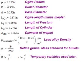
We will first compute the mass for the Sierra MatchKing projectile (tangent ogive) shown in Figure 10. Observe that this projectile has a flattened nose, called a meplat. Because of the meplat, we do not know the full length of the ogive portion of the projectile. As we show below, however, we can use a numerical solver to find the length very easily.
| Source. All units expressed in inches. |
We should review some basic units here.
- bullet mass is expressed in grains, with
- bullet diameter (at least for North America) is expressed in calibers, with one caliber being one thousandth of an inch.
Determination of Ogive Length
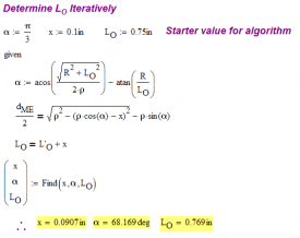
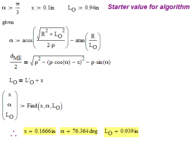
We can use Mathcad to compute the ogive length using its numerical solver. Figure 11 illustrates the calculation. I have defined a length called L' that is the length of the ogive shortened by the meplat. For my equations, I need the length L, which is the length of the full ogive (i.e. not shortened by the meplat). I set up a system of equations that allowed me to solve for L given L' and the meplat diameter.
|
|
Note that I am estimating the density of the lead alloy by averaging two numbers. I have found various specifications for the density of the alloy and I decided to use the average of the upper and lower values for the range I found. Also, these bullets have jackets made of materials (like copper) with lower density than lead. Some also include steel. The MatchKing actually has a hollow tip. Consider the MatchKing cutaway shown in Figure 13.
This will lower the mass of the projectile relative to a solid lead projectile. For my analyses, I will simply use the average of two lead alloy densities.
Mass Calculation
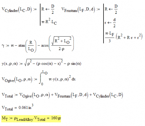
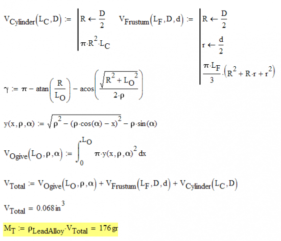
Now that we have the length of the ogive, we can compute the mass of the projectile. Figure 14 illustrates the calculation.
As we can see in Figure 14, the computed mass of 160 grains is within 5 grains of the manufacturer's mass specification. This is well within the range possible due to variations in the density of the bullet alloy and the fact that I am ignoring the presence of a jacket.
Example Two: JLK, 7 mm, 180 Grain Bullet.
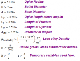
I found the following drawing for the JLK bullet and thought it would be a good example to use to test my algorithm. This bullet has a secant ogive, which is different than the tangent ogive of Example 1 (i.e. it appears to be more tapered). Figure 15 is a dimensioned drawing of this projectile.
| Source. All units expressed in inches. |
Determination of Ogive Length
Figures 16 and 17 show the calculation of the ogive length.
|
|
Mass Calculation
Figure 18 illustrates the calculation of the JLK bullet's mass.
The calculated mass is within 4 grains of the manufacturer's specification of 180 grains. This is well within the range possible due to variations in the density of the bullet alloy and the fact that I am ignoring the presence of a jacket.
Conclusion
This blog post went through the basic geometry of the ogive and derived a set of equations that allow basic physical parameters such as volume and mass to be computed. Two examples were worked that illustrated how the equations could be applied to real problems. This was a good exercise in the use of basic geometry and applying a computer algebra system to solving a real engineering problem.



Your math is correct but the bullet is actually two parts, copper and lead. I think this is the only reason you've got a 5 grain difference.
If you go to sierra's site you'll see what I mean.
http://www.sierrabullets.com/index.cfm?section=bullets&page=rifle&brandID=1
No disagreement. The mass error is most likely caused by errors in my density assumption. The effective density will vary based on any alloying present in the lead and the fact that the jacket is not made of lead. I could expand the model to account for these facts, but the main thrust of the post was to present an application for a computer algebra system.
Thanks for the comment.
Very good article. I have a question. If I know all the dimensions of the bullet except the radius of the ogive (as depicted in fig10) how can I determine what it is? Is there a formula for this?
The ogive volume using calculus is simply the summation of "circles" starting at the base of the ogive to the tip. Since we know that r = 1/2 * diameter then at any point you measure the diameter you can get the radius. Keep in mind the radius will change. This is why the integral is important to getting the volume of the ogive. Thanks Newton.
Thanks a lot for your useful an dfruitful discussions on ballistics. I'm using MathCad as well to apply it on different real-life problems. On ballistics I would like to know if you have discussed previously on your blog (it's huge! well worked!) the effects of the spinning bullet to stabilize the trayectory. I think this can also studied with MathCad (though we are entering in the 3D) and I would like to know your approach as well as if you have a good reference of a mathematical treatment on this fact (besides Coriolis and Magnum... yet): how could we implement drag force, spinning bullet and side-wind (more drag-force, in another direction) in a MathCad worksheet. Thanks a lot!
Full disclosure my background is physics and material science. I have bowhunted my entire life and never wanted to know anything about guns until my daughter wanted to get into it. My experience with ballistics is literally one week old but already I have issues with what is provided to us as a general audience.
Great article and I wanted to say your math is spot on. Calculating density using displacement could probably get us close to a usable coefficient for the bullets we decide to load. Water displacement of the materials (copper, nickel, lead, etc) in there pure forms then getting the displacement of the actual bullet could provide the coefficient. Once we have that then mass is a simple calculation.
As this pertains to drag and getting an accurate coefficient used in BC ratio is more of what I am after. I cannot see how we can use anything but a quadratic drag equation to determine drag and thus the retardation of flight drag throughout. Since the quadratic takes into account loss of mass and these bullets are supersonic then the fluid it travels through, air, will start to mimic water. The difference being the impulse which is the change in momentum BUT we also have to account for the change in mass not just change in velocity.
Sorry to hijack, but this is interesting. Since I am a newby to ballistics this will require me breaking out the old MATLAB and start some experimentation in the Lab (garage and range).
Thanks again for the article.