Quote of the Day
It is failure that guides evolution; perfection provides no incentive for improvement, and nothing is perfect.
— Colson Whitehead
Introduction
Occasionally, I have an engineer come by my cube and unexpectedly present me with an opportunity to do math. A few years ago one of the engineers stopped by with a VERY common type of electrical engineering problem. He had an LVPECL logic device that needed to connect to a CML logic device. Of course, these two logic families have different voltage levels and cannot communicate with one another unless some sort of voltage-level shifting (Figure 1) is performed between the devices. We had been using a level-shifting circuit recommended by an IC vendor, but that circuit had turned out to have some problems (I do not know what these problems were). The engineer posing the question had spent a few hours grinding through the math manually and eventually decided that it was too painful to continue. He knew that I use computer algebra systems like Mathematica and Mathcad, so he asked if I could help. Using Mathcad, the following analysis was performed and we had a solution within five minutes. It was quite a demonstration of the power of modern computer algebra systems.
Analysis
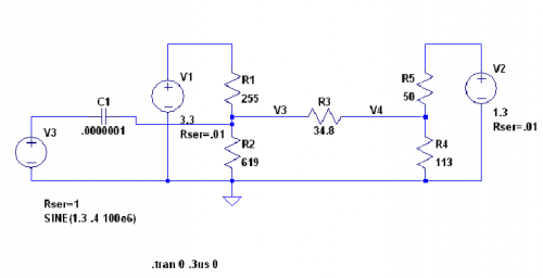
Figure 2 shows the circuit that I was presented with.
From my standpoint, I knew nothing about his problem. I treated this purely as a circuit analysis problem. The engineer told me that this circuit had to meet a number of constraints.
- V1 = 3.3 V (a supply voltage)
- V2 = 1.3 V (another supply voltage)
- V3 = 1.3 V (see schematic)
- V4 = 1.1 V (see schematic)
- Zn3 = 50 Ω (input impedance at V3)
- Reduce the signal level by 1/2 at V4
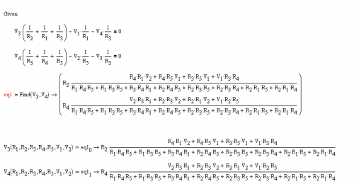
I began by writing Kirchoff''s equations for this circuit in Mathcad and solving for the voltages V3 and V4. Figure 3 illustrates this calculation. This result took me a couple of minutes in Mathcad. The engineer who posed the question had worked hours on it.
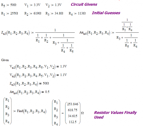
Now that I had my equations for V3 and V4, I can use Mathcad's Solver block to select the resistors required to meet the circuit constraints. Figure 4 shows this calculation.
This completed the analysis and the engineer went away. I assumed everything went well because the engineer went away with a smile on his face. This effort resulted in a bit of humor a few months later. The worksheet was put together quickly so it is not very neat -- here is the source.
Conclusion
A few months after this exercise, I was taking with some engineers about how a circuit card that previously had problems was now performing very well. They mentioned that a level-shifting circuit had been a problem but that the issue had been resolved. I asked who had resolved the problem and they said I had! I had no clue what I was working on during my little analysis effort. It turned out this level shifting circuit had been a problem, and my new resistor values had been incorporated – they worked as expected.
This circuit has now been in production for a number of years. When people ask about whether computer algebra systems are useful to engineers, I always use this circuit as my best example.


Neat, but I think you forgot your attenuation condition!
Good catch! It turns out the equation was actually there, but so poorly positioned as to be covered by the Find command. I have moved things around and now all four conditions can be seen. Thanks for the help.
Pingback: Mathcad Solution to an LVPECL to LVDS Matching Problem | Math Encounters Blog