As you guys know, I've been on a mission to learn how electronic parts work. As an engineer, I have a decent knowledge of certain parts of electronics but I always want to know more. What makes the leviton switches work? How do circuit breaks happen? Why does the amount of voltage matter? I thought I did a pretty good job explaining in part 1 but wanted to clear a few things up.
I noticed that in my post "Learning How Electronic Parts Work" that I neglected to compare my model to reality. I thought I had better rectify this situation because a year from now I will forget what I did and have to reconstruct my arguments. There was more algebra involved than I anticipated. I used Mathcad to perform my analysis and modeling. The figures shown below are all screenshots from my Mathcad model.
Figure 1 shows my logarithm function model (I call it the prototype) and the Maxim representation of their part characteristics, which they specify as the slope and intercept of a line on a semilog plot.
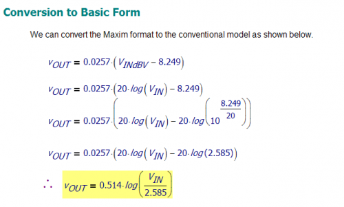
Figure 2 shows how I have beaten Maxim's semilog data into the more conventional logarithmic function form.
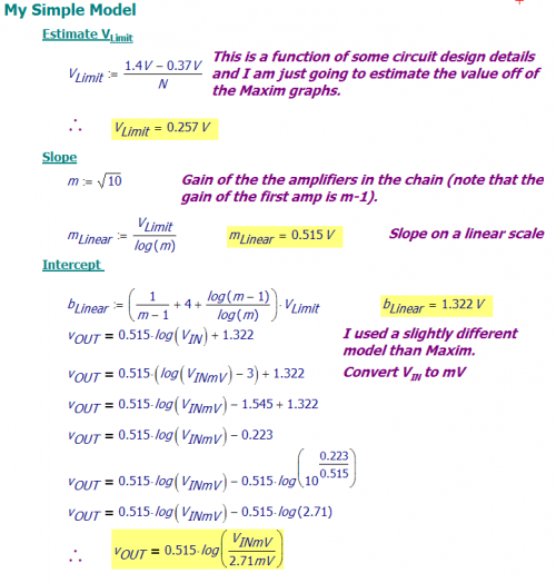
Figure 3 shows the results of my model converted to a standard logarithm function form.
The Maxim specifications and my Mathcad model are in good agreement (thank goodness). You may notice that there is a lot of algebra associated with the use of decibels. Even though I am an electrical engineer and I have to use decibels all day, I really do not like decibels. I am forced to deal with them because that is how electrical systems are specified. I do all my calculations in Mathcad, which helps me keep all my units and logarithmic scalings straight.


Are these screenshots from Mathcad or Maxim? You wrote they are from your Mathcad model, but then you discuss the use of Maxim in the rest of the article. They look like Mathcad.
Thanks,
Mona
Hi Mona,
The screenshots are from Mathcad. I am analyzing a part made by Maxim using Mathcad. That is why you see me mention Maxim all the time.
Mathscinotes