Quote of the Day
If Hitler invaded hell, I would have had a nice word or two for the devil in the House of Commons.
— Sir Winston Churchill, his response when asked why he was saying nice things about the Soviet Union after Hitler invaded the Soviet Union.
Introduction

Figure 1: Typical Thermistor Construction and Symbols (Source).
A common electrical engineering task during the design of a circuit card is designing a way for the circuit to measure its own temperature. Knowing the temperature of a circuit board is important for compensating for component temperature variations and diagnosing heat problems. Normally, I use a thermistor as my temperature probe. A thermistor is a resistor whose resistance varies with temperature (Figure 1). The thermistors that I use have a negative temperature coefficient (NTC), which means their resistance reduces as their temperature increases. In many ways, thermistors are a great sensor: cheap, tough, small, and accurate.
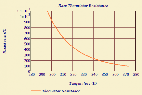
Thermistors have one major drawback – their resistance variation with temperature is non-linear. Figure 2 shows how the resistance of a typical NTC thermistor varies with temperature.
Linearity is a sensor characteristic that is loved by analog engineers. For this kind of problem, it means that calibration is simple (i.e. two points determine a line) and I do not need a processor around to implement complex compensation equations. The resistance characteristic of an NTC thermistor is too non-linear for my application directly. But what if I combined the NTC thermistor with other components in a manner that would somehow tame this non-linear response? This post will look at a common approach to linearizing the circuit response from a thermistor.
Problem Description
All engineering problems begin with determining requirements. Here is how I see my requirements for this problem:
- Limited range of temperatures to be measured
I only need to measure temperature over a limited temperature range (0 °C to 40 °C). This is considered the standard temperature range for indoor applications. - Minimal calibration
Sensors usually require calibration, which is an expensive operation in production. - Generates a voltage that varies linearly (approximately) with temperature.
I want a linear sensor to simplify my calibration. A linear sensor requires a couple of measurements to complete calibration. - Temperature accurate within 5 °C.
This level of accuracy means that I can get by with an approximately linear sensor. - Minimal impact on software
My processor is a very limited microprocessor (i.e. AVR) with minimal memory. I will use an analog-to-digital converter in the processor to read the voltage. I want the conversion from voltage to temperature to very simple. I have neither the memory nor time to require any fancy curve interpolation to get a simple temperature reading. - Minimal Printed Circuit Board (PCB) space because I only have space for a couple 0603-sized (i.e. 0.6 mm x 0.3 mm) components. Instead, you could consider contacting a PCB software specialist company for advice or help with this electrical engineering task (such as Altium for example).
- Minimal cost
I need something that costs pennies. - No integrated circuits.
I am not wild about using an IC in this application. There are quite a few ICs that put out a voltage that is Proportional to Absolute Temperature (PTAT), but they generally require a power supply voltage that I do not have available or they cost too much.
Thermistor Characteristics
The resistance characteristic of Figure 1 can be modeled in a number of ways, but only two are really seen often: the Steinhart-Hart equation, and the ß-Parameter Equation.
The classic approach is the Steinhart-Hart equation (Equation 1). It is a very accurate model. In fact, it is far more accurate than I need.
| Eq. 1 |
where
- a, b, c are parameters that are chosen to fit the equation to the resistance characteristic.
- R is the thermistor resistance (Ω).
- T is the thermistor temperature (K)
While the Steinhart-Hart equation may be accurate, I have found it useless for use by an analog designer in a hardware application. It is simply too difficult to work mathematically without substantial software resources.
The ß-Parameter Equation is much more interesting to an analog engineer. Equation 2 shows the ß-Parameter Model as it is usually seen.
| Eq. 2 |
where
- R0 is the themistor resistance at temperature T0
- ß is a curve fitting parameter.
The ß-Parameter Model is sufficiently accurate for my purposes and is much simpler to work with mathematically than the Steinhart-Hart equation. We will use this model for the remainder of this post.
Thermistor Linearization
Approach
Most thermistor linearization approaches involves adding parallel or series resistors. I will use a thermistor with a series resistor configured as a voltage divider (see Figure 3). This is the simplest linearization circuit that I can think of.
We will be measuring the output voltage (VOut) from the voltage divider, which is given by Equation 3.
| Eq. 3 |
where
- VIN is the voltage divider drive voltage.
- VOUT is the voltage divider output voltage.
- RS is the resistance of the series resistance.
- RT(T) is the resistance of the thermistor.
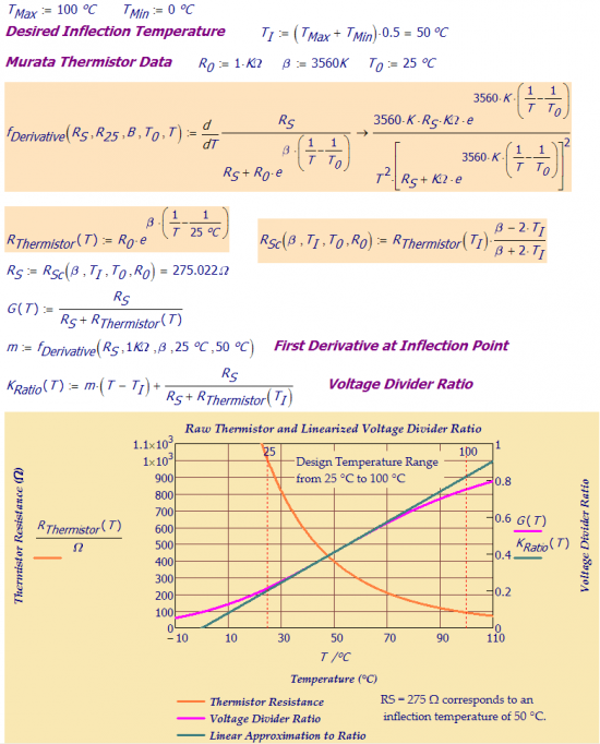
To get an intuitive feel for the how the linearization occurs, you need to consider the asymptotic cases. For low temperatures, RT(T) is large relative to RS and the output is approximately , which approaches 0 as the temperature drops. For high temperatures, RT(T) is small relative to RS and the output voltage approaches VIN. Figure 4 shows the thermistor resistance and the normalized output voltage versus temperature.
Look closely at Figure 4 and you will see an inflection point in the curve (452 Ω and 50 °C in Figure 4). At the inflection point, . After a long, tedious derivation (shown in the Appendix below), one can show that the inflection point can be moved where you want it by changing RS. Equation 4 shows the relationship between the temperature of the inflection point and the value of RS.
| Eq. 4 |
where
- TI is the temperature of inflection.
- T0, R0 ,and ß are thermistor parameters given by the thermistor vendor.
The "rule of thumb" is to select RS to place the inflection point in the middle of your temperature range of operation. As you can see in Figure 4, this placement helps to minimize the maximum deviation from a line through the inflection point. However, it is not guaranteed to be the point of minimum error. When I need that level of accuracy, I use numerical methods to find the RS that minimizes the maximum error.
Example
Figure 5 shows a worked example of my thermistor calculations in Mathcad.
Conclusion
The design of the linearization circuit for a thermistor is a nice use of basic calculus in an engineering application. Hopefully, some of you will find all the details presented useful.
Appendix
I wanted to record my derivation of Equation 4 so I would not have to go through the derivation pain again later, but since it is long and tedious I did not want to put readers through it – an Appendix seemed the appropriate place.
My approach is straightforward:
- Develop an expression for VOUT using the ß-Parameter model.
- Take the first and second derivatives of this expression.
- Set the second derivative equal to zero.
- Solve this expression for RS.
The derivation is shown in Equation 5. I will let the details stand for themselves.
| Eq. 5 | |
You can also derive Equation 4 using Mathcad, which I demonstrate in Figure 6. The main issue with my Mathcad derivation is that many of the details are hidden. However, it took me less than a minute to complete it.


This answer allowed me to design a circuit for a project that has been waiting for the "best available" approach. It took about three minutes and I know it is 'correct'. Don't mention the hours searching because I believed someone must have already solved it. Thank you.
You would be amazed how often I hear things like this. My belief is that if I have a problem then someone else probably has it too. If there is anything I can do to improve my presentation, please drop me a note.
This helped me a lot. Thank you! 🙂
My hope is that these posts help others. Good luck on your circuit work.
Mathscinotes
Pingback: Two-Resistor Thermistor Linearizer | Math Encounters Blog
So beta is left in Kelvin and T1,T0 are left in Celsius when doing the calculation?
Actually I think I figured out it's all supposed to be in Kelvin
All in Kelvin. In fact, Mathcad does all its work in Kelvin.
mathscinotes
This is great information!
Have you analyzed the similar problem where the thermistor and reference resistance are swapped in position? In other words, Rs and Rt(T) are in the top and bottom position respectively. Assuming there are no issues interfacing with the ADC front-end, I’m trying to figure out if we can get a better linear approximation over the same temperature range.
Note: In “Linearizing thermistors with a single resistor” ,Electron, 1981, Burke suggested a method of calculating the optimum value of linearizing resistor for a given temperature range. This method assumes a voltage divider configuration where the thermistor is in the bottom position. Results are shows on page 2 of this document.
USING THERMISTOR TEMPERATURE SENSORS
Thank you
Please see my blog post today. I decided that your question was of enough general interest that I did a whole post.
Pingback: Yet Another Thermistor Discussion | Math Encounters Blog
Hello! Very nice and clean writing. But I do not understand the reason for this linearization. First I think we have to use an Rs in the circuit because there's no other way to measure Rt. So I think the purpose of the Rs is not exclusively to linearize the system.
Then I think most microcontrollers are capable of solving the Steinhart-Hart equasion. From the thermistor table it's possible to determine the a,b,c constant parameters. Measure Vout -> Rt -> T from S-H equasion. Am I right, or not?
Hi Zoi,
One reason to include RS is so that we can measure a voltage rather than directly measure RT's resistance -- a resistance measurement is more work than measuring the voltage. There are circuits that use timing rather voltage (e.g. link). These circuits usually require a capacitor.
You are absolutely correct that you can use a table or even solve an equation if you wish. The Steinhart-Hart equation is very accurate (± 0.1°C), but obtaining that accuracy will require testing at multiple temperature points because each thermistor will have different parameters (a,b,c). For many products (i.e. all of mine), I only have enough time in production to calibrate at the temperature at the time of test – no other temperature will be used. In those cases, linearization is simple, quick, and accurate enough.
I do not always linearize thermistor cicuits – I have often used tables when accuracy is important. If I only need a cheap, approximate answer over a limited temperature range, then I linearize.
mathscinotes
Thank you for your answer. Your blog is fantastic. Your last sentence was the answer I was looking for. If you allow me one more question, how do you calibrate your sensors? Is there a fix, but variable resistor (like potentiometers) in your circuits for adjustments? Or if you use microcontrollers do you upload firmwares with the calculated/measured unique constants? Thanks!
We work very hard to ensure that all calibration is done using constants fed to software. The constants are stored in flash memory. I have been able to avoid all manual potentiometers in my work designs – my home projects are a different matter.
I have used a couple of programmable potentiometers in my work designs. These units are controlled by software.
mathscinotes
hi
Always "inflection point" lies on "row Thermistor Resistance" curve?
why yes? why no?
Thanks
i could understand.
yes.
"inflection point" lies on "row Thermistor Resistance" curve.
Superposition of two curves reveals that "inflection point" lies on "row Thermistor Resistance" curve.
Thanks
Hello. This article is very helpful. I am in the process to design my signal conditioning circuit for NTC Thermistor.
I am not understand how you get the value of the series resistor ?
How 275.022 ohm came from?
The calculations are shown in Figure 4. However, I will repeat them here because you do have to look at Figure 4 pretty closely.
R_Sc (β,T_1,T_0,R_0 ) = ( 25 × e^(3560∙(1/50-1/25) ) ) . (3560-2∙50)/(3560+2∙50)
= (25 × e^(-71.2) ) ∙ 0.9453551913
= (2.993456126 × 〖10〗^(-30) ) ×0.9453551913
= 2.929879288 × 〖10〗^(-30)
I am sorry. I try to paste my calculation here, but it messed up.
I already substitute with the value you gave, but the answer that I got was different.
What I understand is, first I need to calculate the R_thermistor(T). Is it correct I used the value of T as T1 since it is for R_thermistor(T1).
Hi Saif,
I believe the issue you are having has to do with the temperature units – all temperatures must be input in Kelvin. I use Mathcad, which converts all temperatures to Kelvin automatically.
Here is a spreadsheet in Excel that does this calculation. If you do not have access to Excel, the spreadsheet can be imported in a free spreadsheet such as is offered by Google Docs.
mathscinotes
Thank you very much mathscinotes.
You are very helpful.
Just need your thought for this statement,
"By simply adding one resistor in series with the thermistor, the output voltage vs. temperature curve can be linearized. When resistance vs. temperature linearization is desired, the resistor should be connected in parallel with the thermistor."
Because when I try to use parallel resistor approach, I got the same graph as yours which you used series resistor. The output voltage vs. temperature linearized not the resistance vs. temperature linearization .
I wonder why.
You are looking for some insight into how the parallel and series circuits are related. I will try to help out. You can look at this statement a number of ways. Both the series and parallel circuits have the same optimal linearization resistance. However, their temperature characteristics are different. With the parallel circuit, the parallel resistance decreases with increasing temperature. In the series circuit, the output voltage rises with increasing temperature. You can show that the linearization for the series resistance is the same linearization for the parallel combination a number of ways.
Let's assume that we apply a test current to the parallel combination and measure the current. For convenience, let's say our test current is 1 V/Rs. We can now write our output voltage as shown below.
The output voltage, which is proportional to the resistance, is just flipped and shifted from the output voltage of the series circuit. Shifts and flips do not change linearity. Thus, the linearizing resistance is the equal in both cases.
You can just pull out the mathematical artillery and compute the resistance value that gives you the maximal flatness curve. It is the same value as for the series connection.
For completeness, it is worthwhile repeating my work in the original post for the parallel resistance case.
Thank you very much for you notes and explanations. You are very helpful. I will try to understand what you explained in the notes because I need time to understand those methods.
Thank you very much.
it is a nice work sir. please may you help me on how to solve this problem?
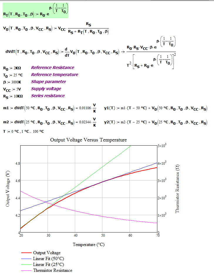
A temperature measuring device consists of Thermistor and 10 kilo Ohm resistor is connected in series across a 5V supply. The voltage across the 10 kilo Ohm resistor is measured by means of very high resistor voltmeter. The thermistor has a resistance 2000 Ohm at 25degree of centigrade temperature and a B value of 3000 at 25degree of centigrade temperature. Determine the rate of change of output voltage with temperature at
(a) 25 degree of centigrade temperature
(b) 50degree of centigrade temperature
I certainly hope this is not a homework problem. However, here is my solution.

thanks alot mathscinotes,, your solution helps me alot.
No problem. I hope you get a good grade.
mathscinotes
Hello mathscinotes,
Can help me clarify my confusion.
What I know, thermistor is highly non-linear.
I made some research and read some articles, they said when you try to linearize the thermistor, you also change the sensitivity of the thermistor
I do understand a bit, but can you explain how its related.
Thank you,
Paul
Linearizing a thermistor ALWAYS causes a reduction in sensitivity. It is the price you pay for linearity. I generally use a linearized thermistor for temperature measurement situations that do not require great sensitivity.
mathscinotes
Now, I am in the process of building my circuit for NTC Thermistor. My approach is by using Wheatstone bridge to measure the resistance change in thermistor, then I connect it with Instrumentation Amplifier to amplify the mV to V and the last part I connect it to low pass filter. So how can i apply the series resistor then ? Do you have any suggestion, since next week in my presentation.
And I test my thermistor with boiling water, its not giving an accurate measurement. I think my thermistor is broken.
Hi,
I have a PTC thermistor (carel model PTC0150000) with sensor type KTY81/121 philips.Please advice how i can make it linear voltage output... Since PTC almost give linear esistance-temp. characteristics,it is advisable to use bridge circuit or with series resistance(2.2 k) would help??
Thanks..Sinil
Pingback: 3D Printer Heated Build Plate Arduino Controller: 6 Steps (with Pictures) - arduino
MY FREND THIS IS THE BEST EXPLENATION I HAVE GET IN THE WED. I AM A FAN OF MATHEMATICS BUT I WOULD LIKE TO KNOW HOW TO RESOLVE THE PROBLEM WITH PIC 16C71 USING INTERPOLATION OR USING TABLE SOME EXAMPLENATION MAY BE GOOD FOR CONCEPTS and curiocity