Quote of the Day
The military don't start wars. Politicians start wars.
— William Westmoreland
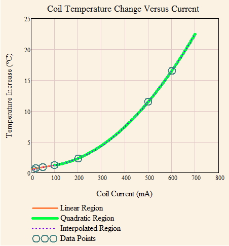
I often have to model the rise of passive component temperatures with respect to some circuit parameter, like current or voltage. I thought I would present here a typical example of how the temperature of a passive part varies with current. In this case, I am feeding a constant current into the coil and I need to know what temperature rise I should expect with this component. I usually model component temperatures using two curves: a linear curve for low current levels, and a quadratic curve for high current levels. This model has worked reasonably well over the years.
Table 1 shows the raw data, which was taken by the coil manufacturer.
Table 1: Temperature Rise Versus Ambient Versus Current.
|
Rise Temp |
|
|
10 |
0.4 |
|
20 |
0.7 |
|
50 |
0.9 |
|
100 |
1.2 |
|
200 |
2.3 |
|
500 |
11.5 |
|
600 |
16.5 |
Figure 2 shows a plot of Table 1 and how I model this data mathematically using two curves.
The size of the linear and quadratic regions varies with the type of part. You can see the same sort of thing with a lead-acid battery (example).
I generally divide the temperature rise characteristics into two regions:
- linear region
At low current levels, there is so little self-heating that the component's internal resistance of the device is not significantly affected by the self-heating. This means the component is behaving as a linear device (i.e. temperature rise that is proportional to current).
- quadratic region
At high current levels, there is enough self-heating that the component's internal resistance is undergoing a significant increase. For a constant current drive, this means that the internal power level is rising over low current levels. It is like compound interest in that more current produces more resistance, which causes more power usage. We are entering a region where positive feedback is becoming a serious consideration.
This is just a quick example that I thought would illustrate how engineers model these sorts of things.


