
Quote of the Day
No plan for software development survives contact with the code – double so for legacy code.
— Comment from a software developer. This is a modification of Helmuth von Moltke’s "No plan survives contact with the enemy."
Introduction
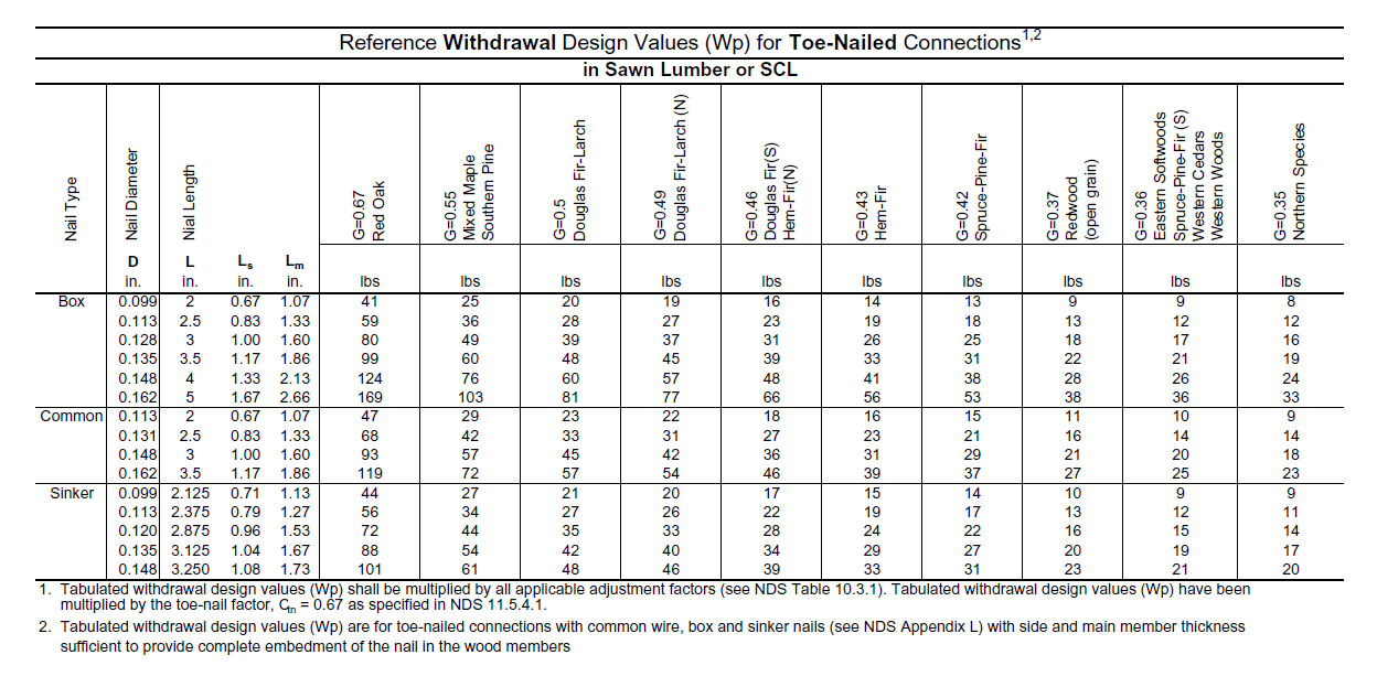
Figure 1: Withdrawal Force Rating for Various Nails and Wood Species (Source).
I have been reading some specifications on fastener requirements in carpentry. To ensure that I understand what I am reading, I decided to see if I could duplicate the design values for nailed connections. In this post, I will duplicate a table (Figure 1) for the withdrawal force ratings of various nails when used in a toe-nailed connection. In general, I try to avoid nails with a withdrawal load, but it is an allowed connection and it was easy to duplicate the results in a National Design Specification (NDS) document. I will be performing a similar computation for the lateral load rating in a later post. My Mathcad source and a PDF are stored here.
I do want to mention that I find the NDS documents to be models of technical exposition. Nice job folks!
Disclaimer: I am NOT a structural engineer. I am just a guy who finds the subject interesting. If you have structural questions, contact a structural engineer.
Background
Toe-Nailed Connection Geometry
Figure 2 shows how the withdrawal and lateral forces on a toe-nailed joint are defined. It also defines the terms that are critical to a toe-nailed joints strength.

Figure 2: Geometry of a Toe-Nailed Connection (Source).
Formula for Nail Withdrawal Force
Figure 3 shows the formula used to generate the withdrawal force table values (Source).
| Eq. 1 |  |
where
- G is the specific gravity of the wood (unitless).
- p is the penetration depth into the cross-member (in).
- d is the diameter of the nail (in).
- FW is the withdrawal force rating of the nail (lbf).
- Ctn is the withdrawal force reduction due to this being a toe-nailed connection (unitless).
Analysis
Solution
Since I am just evaluating a formula at various points, there is not much analysis involved. The solution mainly involves getting all the variables setup properly, which I show in Figure 3.

Figure 3: Calculation Setup and Solution.
Presentation
I generally do not use Mathcad to present tables of data – Mathcad's formatting capabilities are too limited. However, you can use an Excel component within Mathcad, which allows you to use the all of Excel's rich formatting features. Figure 4 shows how I put together a table using Mathcad and an Excel component that looks very similar to the NDS table shown in Figure 1.
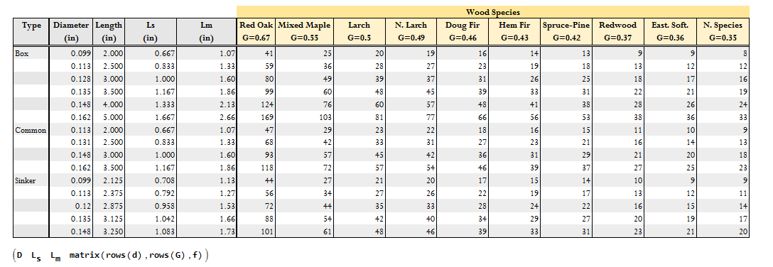
Figure 4: Excel Used to Present the Data.
Conclusion
I think I understand where the withdrawal force rating table came from. It is simple in that there is only one formula to evaluate. In the case of the lateral force rating, there are multiple formulas to evaluate. That will be a topic for a later post.
Hi, I happened to notice that your calculated column for G=0.36 Eastern Softwoods (your 9th calculated column in Figure 3) is off by one or more numbers from the NDS table. Round off error?
You are sharp-eyed reader. The second I looked at the set of specific gravity values, I saw the error. All fixed. Thanks a bunch!!
mathscinotes
Pingback: Lateral Force Rating for Various Nails | Math Encounters Blog