Quote of the Day
The Martian is the best advert for a career in engineering I've ever seen.
- Brian Cox (physicist), tweeted this review of 'The Martian' movie.
Introduction

Figure 1: Propane Heater I Just Purchased (Source).
I have some woodworking I need to do, and my little woodshop is in my garage. Unfortunately, Minnesota is quite cold at the moment, and working in the garage is not comfortable. After decades of working out in the cold, I decided it is time to get a small heater to make things a bit more comfortable.
I have used propane for years with my barbecue grill, but I have never used it for heating a space. I know that there is an Ashland propane delivery provider for people who heat their space this way, but here I just went and got one when I was out. While at university many decades ago, I worked in construction, and we used propane heaters to make working in partially completed homes more comfortable in the winter. I went to Home Depot and purchased the propane heater shown in Figure 1. It is rated to put out 30K to 40K BTU/hr. This should provide enough heat to warm my garage so I can work in it comfortably. I like the fact that it is small, and I can easily store it during the summer. I have too much stuff to manage as it is, and I do not need any more big stuff.
Background
Definitions
- Tare Weight (TW)
- Tare weight, sometimes called unladen weight, is the weight of an empty vehicle or container (Source).
- Commercial Propane
- This product consists of a hydrocarbon mixture containing predominantly propane (Source).
- Water Capacity (WC)
- The water capacity is how much water the propane tank will hold in pounds. For example, the "WC" stamped on the tank followed by a number such as "47.6" means the tank will hold 47.6 pounds of water. (Source).
Tank Construction
Figure 2 shows the internal construction of a typical 20 lb propane tank.

Figure 2: Propane Tank Construction (Source).
Appendix B provides some information on the how the pressure in a propane tank varies with temperature.
Analysis
Volume of Propane in a 20 lb Cylinder
My old propane tank is shown in Figure 3. It has a WC=47.6 lbs and TW=18 lbs.

Figure 3: Rating on My Propane Tank.
I can compute the weight and volume of propane in this tank as shown in Figure 4.

Figure 4: Demonstration of Why a 20 lb Tank is Named Such.
20% Safety Margin
I found the following statement in this document.
A tank filled with a volume of 80% liquid phase at 0 C will be full at a temperature of 60 C. At the same time, the density of propane in the liquid phase decreases from 530 to 430g/l.
Requiring 20% of margin reserve allows the propane to expand when the temperature rises. Figure 5 shows how I confirmed this statement using the propane density versus temperature relationship I compute in Appendix A – I thought it was a bit messy to include in the main post.

Figure 5: Verification of 60 C Temperature Rise Filling a Tank.
In Figure 5, I derive a rate of 1.9% volume expansion for every 10 F of temperature rise, which assumes a constant mass. The Wikipedia lists 1.5% volume expansion for every 10 F. My value is in the ballpark, but not as close as I like to be.
Operating Time At Maximum BTU Generation Rate
Figure 6 shows my estimate for the amount of heating time I should expect from a 20 lb tank of propane – 10.8 hours. The energy density of propane comes from this source.

Figure 6: Estimate Run Time Calculation.
The 10.8 hour value is also quoted in the heater manual (Figure 7).

Figure 7: Heater Manual Run Time Specification.
Conclusion
I like to understand a bit about any product I use. This analysis gave me a bit of insight into how propane is used for space heating.
Appendix A: Liquid Expansion Model
Since I wanted to understand how propane expands with temperature, I need some information. I found this excerpt on the web that provide a functional model based on curve-fitting data.
| Eq. 1 |  |
where
- A, B, n, TC are curve-fit generated parameters.
- T is the temperature in Kelvin.
Unfortunately, I was not able to find parameters for propane (C3H8). So I decided to put together my own model. The model of Equation 1 is a bit difficult to fit because it has some parameters that are not independent. For my work here, I will use the model shown in Equation 2.
| Eq. 2 | 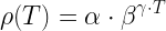 |
where
- α, β, and γ are curve-fit generated parameters.
I searched the web and found some density data points for commercial propane, which is not pure propane because it also contains other fuels like butane and methane. Figure 8 show the results of my curve-fitting exercise.

Figure 8: My Curve-Fitting of Propane Density Data.
Figure 9 graphically shows the quality of the curve-fit to the data. Note that in this limited temperature region, a linear model would have sufficed.

Figure 9 Curve-Fit Vs. Raw Data.
Appendix B: Tank Pressure Vs. Temperature
Figure 10 shows how the tank pressure varies with temperature.

Figure 10: Tank Pressure Versus Temperature (Source).