Quote of the Day
Patience is also a form of action.
— Auguste Rodin, Sculptor
Introduction

Figure 1: Sextant is Used by
Navigators To Make Celestial
Observations (Source).
I love to read stories of the sea and about the voyages made during the age of sail. I personally have never thought that I would have an opportunity for ocean sailing, but I recently began working with an engineer who is an avid sailor and teacher of sailing. He has sailed all over the world and recently trained another engineer in my group to sail. This newly trained sailor just returned from a trip to Bora Bora, which he found to be enjoyable and the sailing uneventful.
My discussions with this sailing instructor have given me some hope that I may yet get to do some sailing. This hope has reawakened my interest in some of the traditional technologies of sailing, like ropework and celestial navigation.
This post is the first in a series on correcting sextant (Figure 1) measurements for impairments. There are a number of measurements impairments: index error, refraction, and dip. This post will look at the impairment known as dip.
Background
Definitions
- altitude
- The angular distance of a celestial object above an observer's horizontal plane . There are published tables of the altitudes of various celestial objects. However, it is difficult to obtain a stable horizontal reference on a moving ship. The horizon provides a very stable reference and we can use a sextant to accurately measure the altitudes of celestial objects with respect to the horizon. Figure 2 shows the relationship between the horizontal and the horizon. The are related through the angle called dip.

Figure 2: Illustration of Dip With Respect to Horizontal (source).
- dip of the horizon
- Dip of the horizon is the the angular depression of the horizon below the horizontal plane. If we were taking sights on a stable land site, we could measure altitudes using a theodolite with its horizontal established using a bubble level. At sea, however, nothing is stable except the horizon. We use a sextant at sea to measure the altitude of a celestial object with respect to the horizon and then use our dip calculation to change the altitude reference from the horizon to the horizontal.
- dip short of the horizon
- There are times when it may be necessary to measure the altitude of a celestial object even though we do not have a visible horizon because of an obstruction. However, if we the distance to the obstruction we can calculate a dip value that will allow us to correct our sextant measurement. We refer to this dip value as the dip short of the horizon. Typically, we will measure the altitude relative to the water level at the obstruction, which is a relatively stable reference.

Objective
I will be deriving commonly used formulas for dip to the horizon and dip short of the horizon. I should point out that I have seen many formulas for these dip values and I arbitrarily picked two formulas to investigate more closely here.
Analysis
Standard Dip Short of the Horizon Table and Formula
Common Presentation
Figure 3 shows the values for the dip short of the horizon using a common table (Norie's) and formula (Bowditch). They give similar, though not identical results. In Figure 3, I show how you can take Norie's tabular data, fit it to a Bowditch-like formula, and you find that Norie's table and Bowditch's formula produce similar results.
I should note that the results for dip short the horizon used in both Norie and Bowditch ignore refraction. This makes sense because most obstructions used for navigation purposes would be relatively near, and the effects of refraction will be minimal.

Figure 3: Dip Short of Horizon Table and Formula.
Figure 3 also shows a snippet of Bowditch's formula dip short of the horizon, which is given by Equation 1.
| Eq. 1 |  |
where
- d is the distance to the obstruction [nautical miles].
- h is the height above sea level of the observer's eye [feet].
- dshort is the dip short of the horizon [arcmin].
Derivation
Figure 4 shows the geometry of the dip short of the horizon situation.

Figure 4: Dip Short of Horizon Measurement Scenario.
Figure 5 shows how you can derive an expression very similar to that of Bowditch's.

Figure 5: Derivation of Bowditch's Dip Short of Horizon Formula.
While the expression shown in Figure 5 is not identical to that in Bowditch, it is quite close.
Dip to the Horizon Formula
The dip to the horizon formula is shown in Figure 6 (source).
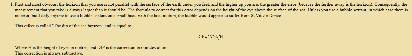
Figure 6: Commonly Used Dip of the Horizon Formula.
The derivation of this formula is similar to the dip short of horizon formula, but now we will model refraction. For the dip to the horizon, I have only seen formulas that are functions of the square root of the observer's height h.
Equation 2 shows a common expression for dip of the horizon, dhorizon.
| Eq. 2 |  |
Figure 8 shows how you can derive Equation 2.

Figure 8: Derivation of Dip to Horizon formula.
My derivation yielded a function similar in form to the that shown in Figure 6, but with a larger coefficient term. The coefficient term is a function of the atmospheric conditions, and I assume that my atmospheric assumptions are different. The results differ by ~10%, which is well within the bounds of atmospheric variation.
Conclusion
I believe that I understand where the dip tables and formulas come from. I also understand that some dip equations take refraction into account (Figure 7) and some do not (Figure 3). Dip was a good impairment to use to kickoff my learning process – next are index error and refraction.


 . Since we know the size of the sheet of paper, we can compute the FOV. The results obtained are similar to the previous two methods, at least considering how crudely I took the measurements.

 underwent fission in the