Discussion of Math Associated with MH370 Search

Here are a couple of web sources on how the course of MH370 was determined.

Some of these transponder-based, distance analyses reminds me a bit of the Oboe navigation system used during WW2.

The Doppler shift work is interesting and I quote here from the Wikipedia. One good aspect of this approach is that it is easily testable using actual aircraft tracking data.

After establishing the "corridors" where the aircraft may have been located at the time of the final handshake, Inmarsat proceeded to further analyze the signals received by its ground stations during the handshakes with Flight 370. This analysis focused on the frequency of the signal expected from the aircraft and the actual frequency of the signal received, known as the burst frequency offset. The burst frequency offset results from the change in frequency of an electromagnetic wave to an observer due to the motion of the source, known as the doppler effect. A baseline of system characteristics for the aircraft, satellite, and ground station could be calculated from several messages sent by Flight 370 while on the ground in Kuala Lumpur and during the early stage of the flight when its location was known.The burst frequency offset would change not only based on the aircraft's airspeed, but also its position along the identified arcs and direction. To test its theory, Inmarsat calculated positions for six Boeing 777 aircraft flying in various directions on the same day and compared those calculations to actual positions, resulting in a good match. Using the results of that analysis, there was a good correlation of the expected and actual burst frequency offsets with the aircraft flying south over the Indian Ocean (along the southern corridor at the time of last transmission) and poor correlation if the aircraft flew north. After factoring in the satellite's small movements in relation to the earth, which were not taken into account in the earlier calculations, the northern corridor was ruled out completely.

Posted in Navigation | Comments Off on Discussion of Math Associated with MH370 Search

6000 Meter Depth Rating on Ocean Search Gear

Quote of the Day

The sea is notoriously unforgiving, but it reserves its harshest penalties for those who venture beneath its surface.

— U.S. Navy veteran A.J. Hill


I have been watching the news coverage of the search for the missing Boeing 777 (aka flight MH370) over the southern Indian Ocean. I have heard quite a bit of news coverage referring to oceanographic search gear that will operate to 6000 meters depth (example 1, example 2). Here is one quote (source):

One system, called a "Towed Pinger Locator", is towed behind ships and is used to listen for downed Navy and commercial aircraft at depths of up to 20,000 feet (6000 meters), according to the U.S. Navy's website.

Ocean search gear depth standards are based on the percentage of the ocean bottom that the gear can explore. In the case of a 6000 meter rating, that gear can cover 95% of the Earth's ocean-covered surface. The key to understanding where this coverage percentage comes from is to look at the hypsograph of the Earth (Figure 1).

Figure 1: Hypsograph of the Earth (Source: Wikipedia).

Figure 1: Hypsograph of the Earth (Source: Wikipedia).

A hypsograph plots the proportion of land/sea area that exists at each elevation/depth. You cannot read the 95% directly off of Figure 1. You need to compute a conditional probability. I illustrate this calculation in Equation 1.

Eq. 1 \displaystyle P\left( {\text{Prob}\le \text{6000 m}}/{\text{ProbOcean}}\; \right)=\frac{P\left( \text{Prob}\le \text{6000 m}\cap \text{ProbOcean} \right)}{P\left( \text{ProbOcean} \right)}
\displaystyle =\frac{97.0\%-29.2\%}{100\%-29.2\%}=\frac{67.8\%}{70.8\%}=95.8\%

where

This result is close enough to 95% for my purposes -- certainly when you consider the kind of data I am using.

I have great sympathy for those building gear that works down to 6000 meters -- this is a difficult task. The deep ocean is very unforgiving.

Posted in Underwater | 1 Comment

Frost Depth Deeper Than Normal This Winter

Quote of the Day

Maybe not today..., maybe not tomorrow..., but someday... soon; ... and for the rest of your life ...

- Rick Blaine, Casablanca.


I was in my home town of Osseo this weekend to do some computer work for my mother. As I drove through town, I noticed many signs of water system maintenance (see Figure 1). This is a sign that the winter this year was a hard one - the soil froze so deep that the water pipes froze and burst. This can bring about different types of leaks to your home and surrounding areas such as slab leaks, detecting slab leaks are important and there are signs to look out for in your area, for instance, cracks, raised water bills, hot spots on the floor, etc. If this happens, contact a plumber local to you. You can search for a plumber by clicking plumber near me here.

Frozen water pipes happen every year. Households who don't take precautions often get their pipes frozen and the ice expanding causes them to burst and leak. You would then have to get your leak fixed and remember not to do the same the next year. It is also important to remember that this can happen to households in countries from all over the world, so you should always have the relevant precautions and knowledge in place in case it does. For example, if you live in Sydney, then you may want to have a look at the causes of leaky pipes in Sydney homes to put yourselves in the best possible position in having well-working pipes for the winter season. So what's the big deal now? Well, this year it's the actual main water pipes that are freezing; not the small household ones.

Figure 1: Osseo Road Work.

Figure 1: Osseo Road Work.

In my region, state regulations require that we bury water pipes 48 inches deep. Since the frost depth in the southern counties of Minnesota is stated as 42 inches, I have never seen problems like this before. However, this year the frost depth went down to 5 feet, hence the problems with pipes freezing in Osseo. The northern counties of Minnesota do have a 5 foot frost depth specification.

The Osseo water pipes that froze were all in the streets. We had a massive amount of snow this year, which insulated the pipes that run under the lawns and into homes. However, the streets were kept clear of snow and there was no insulating layer of snow on the streets to prevent the frost from going very deep.

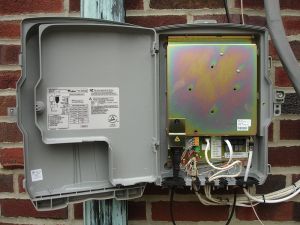
Figure 2: Wikipedia Picture of an ONT.

Figure 2: Wikipedia Picture of an ONT.

I frequently have to deal with issues related to frost depth and fiber optic deployments. In clay soils, I see as much as 9 inches of frost heave. I have seen this frost movement tear the fiber out of the Optical Network Terminal (ONT).

Frost heave can damage much more substantial structures than an ONT. I had a conversation with a building inspector who said that he had seen Sonotube foundation piers split in half by frost heave. Figure 3 shows my sketch of the scenario he described. The frozen soil grabs the upper section of the pier and pulls it up, while the footing stays in place. This tears the pier in two.

Figure 3: Illustration of How A Pier is Broken By Frost Heave.

Figure 3: Illustration of How A Pier is Broken By Frost Heave.

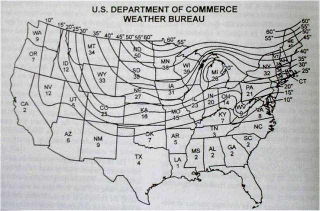
I have included an old US government frost depth (or line) graph in Figure 4 so that you can see the frost depth in your area.

Figure 4: Old Weather Bureau Contour Map of Frost Depth.

Figure 4: Old Weather Bureau Contour Map of Frost Depth.

Posted in Construction | 1 Comment

Using a D-Size Battery String for a UPS Energy Source

Quote of the Day

If there is one thing more than another for which I admire you, it is your original discovery of the Ten Commandments.

— Thomas B. Reed to the youthful Theodore Roosevelt about his self-righteousness


Introduction
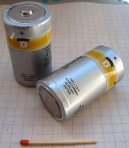
Figure 1: Picture of a Standard D-Cell (Wikipedia).

Figure 1: Picture of a Standard D-Cell (Wikipedia).

I am looking at supporting an Uninterruptible Power Source (UPS) that uses twelve D-size alkaline batteries for its energy source. Telecom service providers like D-size alkaline batteries because their subscribers can purchase them at many local grocery stores. They contain no harmful material and can be tossed in the trash. Service providers currently use a Sealed Lead-Acid (SLA) batteries. SLA batteries are not as widely available and and they contain lead, which must be recycled. However, SLA batteries are convenient because you only need one battery and it is fairly compact.

I thought it would be useful to show you the kind of mathematics that goes into evaluating a battery for use in a UPS application. This is my first application for a D-size batteries. My only contact with them goes back to the late 80s when my children had a CD player that used six D-size batteries. I just remember the batteries as being really big.

Background

Size of a D-Battery

Figure 2: Mechanical Drawing of a D-Size Battery.

Figure 2: Mechanical Drawing of a D-Size Battery.

Figure 2 shows a dimensioned drawing for a D-size battery. D-size batteries are the largest of the cylindrical batteries that are commonly available in grocery stores in the United States. In addition to being large in volume, they are also fairly heavy at 144 grams (5.1 ounces).

The primary reason that some service providers want to use D-size batteries is to ensure that their customers have easy access to replacement batteries. In the US, D-sized batteries are available at many stores (e.g. grocery, gas stations, department, hardware, automotive, etc). However, SLA batteries are not nearly as available − people usually buy them online or at some hardware stores. However, hardware stores are not nearly as common as grocery stores or gas stations.

Figure 3 shows how the D-size battery compares in size with other commonly seen battery sizes.

Figure 3: Comparison of Common Battery Sizes (Wikipedia).

Figure 3: Comparison of Common Battery Sizes (Wikipedia).

The use of D-size batteries for backup power in Fiber-to-the-Home (FTTH) applications has been done before. Marconi used them for an early system. For reasons that I have never fully understood, that system was not commercially successful. However, those folks (like George BuAbbud) got a lot of things right in their design. It was a case of being a little too far ahead of where the market was.

Critical Battery Voltages

There are three battery voltage specifications that will be important for our discussion.

Nominal Cell Voltage (VNom)
This is the labeled battery voltage. For an alkaline battery, it is 1.5 V.
Open Circuit Voltage (VOC)
The open circuit voltage of a battery is the cell voltage of a fully charged battery with no load. For an alkaline battery, this voltage varies from 1.50 V to 1.65 V. The variation is caused by minor differences in concentrations of the materials used in the specific battery.
Cutoff Voltage (VCO)
The cutoff voltage is the cell voltage at which the battery is considered fully discharged.

For the discussion to follow, I will assume that VOC = VNom.

Energy Capacity

One of my tasks is to estimate the run-time of an Optical Network Terminal (ONT) when it is powered by twelve D-size batteries connected in series. The ONT is in backup mode and it will apply a constant load of 9 W to the battery string. My analysis will be based on Figure 4 from this battery specification.

Figure 4: Run-Time of a D-Size Battery As a Function of Load Current and Cut-Off Voltage.

Figure 4: Run-Time of a D-Size Battery As a Function of Load Current and Cut-Off Voltage.

Capacity Retention

Most of the work I do involve Telcordia specifications that mandate a backup time of 10 hours from a new battery and 8 hours from an aged battery. Thus, I plan on replacing the batteries when they have lost 20% of their capacity. The capacity loss from an alkaline battery is often stated to be 3 %/year (Figure 4 - Source).

Figure 5: Alkaline Capacity Degradation with Time.

Figure 5: Alkaline Capacity Degradation with Time.

Analysis

Battery Capacity as a Function of Cut-Off Voltage

Approach

My analysis will be very similar to that performed in this blog post on laser slope efficiency. I am most interested in determining the run time of this twelve-battery pack as a function of the cut-off voltage. The cut-off voltage is important to me because my power supply can only run down to ~10 V, which means my cut-off voltage will be \displaystyle {{V}_{CO}}={}^{10\text{ V}}\!\!\diagup\!\!{}_{12}\;=0.833\text{ V}.

My analysis approach is simple.

  • Digitize the curves in Figure 4 using Dagra.
  • Create a two-dimensional interpolation of the digitized data from Figure 4 using Mathcad.
  • Create a graph of run-time versus cut-off voltage.

Digitized Version of Figure 4

Figure 6 shows my digitization process.

Figure 6: Digitized Version of Figure 4.

Figure 6: Digitized Version of Figure 4.

Figure 7 shows how my digitized data looks when plotted in the format of Figure 4. They look identical.

Figure 7: Plot of My Digitized Data.

Figure 7: Plot of My Digitized Data.

Generate 2-Dimensional Interpolation

Figure 8 shows the Mathcad program that I used to perform the 2-dimensional interpolation.
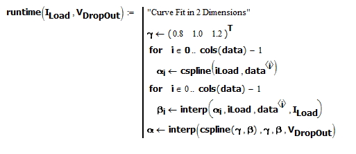
Figure 8: 2-Dimensional Interpolation.

Figure 8: 2-Dimensional Interpolation.

Plot of Run-Time Versus Cut-Off Voltage

Figure 9 shows my graph of run-time versus cut-off voltage. My chart of battery performance assumes a constant load current. Because the battery voltage is always reducing and my ONT's power supply draws a constant power level (i.e. switched mode power converter), the current into my ONT is always varying. I will approximate this current with an average value.

Figure 9: Run-Time Versus Cut-Off Voltage.

Figure 9: Run-Time Versus Cut-Off Voltage.

This chart shows that I will have no problem meeting my 10 hour run-time requirement with a cut-off voltage set at 0.833 V per battery. I can even raise my power supply's cut-off voltage a bit if that will reduce my product cost.

Replacement Time

The replacement time is determined by the 3 % loss of capacity per year. Since I must replace the battery when the loss is 20 %, this means that I will get 6.66 years of service from this battery string before I must replace it. I typically expect to replace batteries every five years. So the D-size alkaline batteries have plenty of retained capacity.

Conclusion

The D-size alkaline battery can be an effective backup energy source for an ONT. My analysis here was strictly technical, but ultimately it will be economics that determines whether the market moves this way. I still have this analysis to perform.

Posted in Batteries, Electronics | Comments Off on Using a D-Size Battery String for a UPS Energy Source

A Simple Frequency-to-Voltage Converter

Quote of the Day

We are what we repeatedly do. Excellence, then, is not an act, but a habit.

- Aristotle


Introduction

Figure 1: Explanation for Why I Need a Voltage-to-Frequency Converter.

Figure 1: Explanation for Why I Need a Voltage-to-Frequency Converter.

I often build small electronics projects for use around my home. I recently put together a small sensor interface that generates an output sine wave with a frequency proportional to the sensor's inductance. At my receiver, I want to convert that frequency to a voltage that is proportional to the sensor's inductance. I want to send out a text message when the value of the sensor's inductance passes through a threshold level – I am detecting the presence of a car (Figure 1).

Since this is a home project, I want to keep it simple and cheap. This blog post documents how I designed this circuit.

Background

The circuit I used is very slight variation on a charge pump circuit I saw years ago in the great little book called "Electronic Designer's Handbook" by Thomas Hemingway (Figure 13.5). This little gem can be viewed online here. The only change I made to this circuit was to shift the voltage levels so that my input signal can be positive.

I will derive an expression for the input frequency-to-output voltage transfer function that is a bit more accurate than what Hemingway derives. However, this is his circuit and his book is still worth reading for those interested in transistor-level design. As you can see, this book was first published in 1966 and I still use it nearly fifty years later.

Analysis

I will focus on my simulation results in this blog post section. Appendix A contains measured data from a working circuit in the field.

Schematic

Figure 2 shows an LTSpice schematic of the circuit I put together.

Figure 1: Simple Frequency-to-Voltage Converter.

Figure 2: Simple Frequency-to-Voltage Converter.

Theory of Operation

Qualitative Description

The circuit operation is fairly straightforward.

  • When the input signal goes low, C1 charges through D1. It is critical that C1 charge quickly relative to the period. This circuit depends on the transfer a fixed quantity of charge at the same rate as the input signal. This means that the charge transfer rate (i.e. current) is directly proportional to the input frequency.
  • When the input signal goes high, C1 discharges through Q1 into C2. C2 will have enough capacitance to ensure that it changes little when C1 discharges into it. This will provide the filtering we need to for a smooth output voltage.
  • The RC filter composed of R1 and C2. R is critical in determining the gain (i.e. slope) of the output voltage versus frequency curve. At equilibrium, the charge lost through R1 for each input cycle exactly equals the charge on C1.

I included my simulation results below that clearly shows each of these operations occurring.

If you seek a more detailed narrative description of how this circuit work, see the discussion comments below. A reader put together an excellent theory of operation on the circuit.

Mathematical Details

Figure 3 shows my derivation of a formula for the frequency-to-voltage conversion process.

Figure 2: Derivation of Frequency-to-Voltage Conversion.

Figure 3: Derivation of Frequency-to-Voltage Conversion.

Simulation Results

Single Simulation Result

Figure 4 shows my simulation results. To see these results clearly, you need to click on the image. The circuit operates exactly as described above.

Figure 3: Simulation Results.

Figure 4: Simulation Results.

Linearity Measurements

Figure 5 shows the linearity that I measured on the simulator. I predicted the slope of my voltage conversion to be 1.08 in Figure 2. My simulation shows 1.095, which means an error of ~1.4%. Not too bad.

Figure 4: Plot of the Linearity of the Frequency-to-Voltage Conversion.

Figure 5: Plot of the Linearity of the Frequency-to-Voltage Conversion.

Conclusion

This circuit is a critical part of a small home sensor system that I have put together. Here is a quick description of my sensor system.

  • I built a metal sensor that is composed of a coil of wire (i.e. inductor) whose inductance decreases when a metal object comes near -- the inductance decreases because of how currents are induced in the metal object. This complex electrical process involved the use of specialist electronic tools such as wire strippers (wirestriper).
  • I built an oscillator which puts out a digital signal with a frequency that is proportional to the inductance of my wire coil.
  • The circuit described here converts the digital signal's frequency to a voltage level.
  • I use a Schmitt trigger to generate an alarm when the voltage from my frequency-to-voltage converter exceeds a value that I have set.

Appendix A: Some Empirical Data from a Circuit I Built

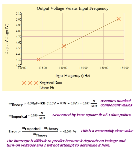
Figure 6 shows 3 data points from a version of this circuit that I am using for a home project. This particular application had C1 = 0.001 µF and R1 = 4 k?. You can see that the response is quite linear, the measured and predicted slopes were within experimental error, and it is working well in my application.

Figure 5: Three Data Points from a Quick Lab Test I Did.

Figure 6: Three Data Points from a Quick Lab Test I Did.

Save

Save

Save

Save

Posted in Electronics | 41 Comments

Population Occurrence Frequency Math

Quote of the Day

Do what you can, with what you have, where you are.

— Theodore Roosevelt


I was reading an article on autism and the article mentioned that autism is much more prevalent in boys than girls. This article states that

The Centers for Disease Control and Prevention has stated that about 1 out of every 88 children are diagnosed with ASD [Autism Spectrum Disorder]. The disorder also affects 1 in every 54 boys, while in girls the rate is 1 in every 252.

I thought I would take a quick look at how the value "1 out of every 88 children" is computed.

In the childhood years, the number of boys slightly exceeds the number of girls. The Wikipedia has table of the gender ratios in each country. This article I am reading is about the United States, and our gender ratio for children under 15 is listed as 104 males to 100 females.

I can use Mathcad to compute the overall population ratio given the girl and boy autism ratios, and the ratio of boys to girls. Figure 1 shows my calculation. These calculations are rough because actual populations ratios are not integral. All of the ratios listed in the article are approximate.

Figure 1: Calculation of Overall Populaton Ratio for Autism.

Figure 1: Calculation of Overall Populaton Ratio for Autism.

So I see where the ratio 1 in 88 children comes from.

I know parents who are dealing autism, Asperberger's syndrome, and ADHD. I have great sympathy for their situation. Some correlation has been found with the prevalence of Asperberger's syndrome with engineers and mathematicians. I have no doubt about this − I have plenty of anecdotal evidence.

Posted in General Science, Health | Comments Off on Population Occurrence Frequency Math

Paper Mechanism Project I Have to Build

I think this interrupted motion paper machine is really interesting. This is on my list for a project. If you want to see other projects like this, got Robert Ives' web site.

Posted in Paper Machines | Comments Off on Paper Mechanism Project I Have to Build

Schmitt Trigger Design Math

Quote of the Day

No. I would either have to embarrass too many people, or I would have to lie. I refuse to do either.

— General George C. Marshall's response when offered $1M to write his memoir on WW2.


Introduction

I have a home project that requires me to design a Schmitt trigger circuit. There are numerous places on the web where you can find design equations for the Schmitt trigger constructed using an open-drain comparator. Unfortunately, these design equations do not model the output low-level saturation voltage of the comparator and in my application I need to be concerned about this voltage. My objective is to determine formulas for the resistors in the circuit as a function of the various threshold and output voltage levels I require.

Figure Y: Otto Schmitt as I Knew Him.

Figure 1: Otto Schmitt as I Knew Him.

As I have mentioned before, I met Otto Schmitt (Figure 1) when I was an undergraduate. As one of so many clueless undergraduates, I had no idea who I was talking to when I met him. He just seemed like another kindly old professor at the time. His office was in a decrepit structure called the Temporary Engineering Annex, which were WW2-era buildings that eventually were torn down. As I came to know more about him, I realized what a major league engineer he was. The University of Minnesota is starting to put together a web memorial to him at this location. I did find a pretty good discussion of his life and accomplishments at this web site.

I have been fortunate to meet and be influenced by people like him throughout my life. Hopefully my sons will be able to say similar things about their upbringing and education.

Background

Schmitt Trigger Description

The Wikipedia defines the Schmitt trigger circuit as

A comparator circuit with hysteresis, implemented by applying positive feedback to the non-inverting input of a comparator or differential amplifier.

Comparators are circuits that make decisions − they decide a one voltage is larger or smaller than another voltage called the reference or VRef. In a noise-free environment, these decisions would be unambiguous. However, the real-world is full of noise and this noise can make the comparator output toggle wildly when input voltage is near VRef. This noise-stimulated toggling is usually a problem for the circuits monitoring the comparator output. The Schmitt trigger is designed to alter its reference level after the output switches so that noise will not cause further switching.

Figure 2 shows the output versus input characteristic of an inverting Schmitt trigger circuit. Notice how positive-going signals will have their threshold level lowered and negative-going signals will their threshold level raised.

Figure 2: Input Versus Output Characteristic of a Schmitt Trigger.Figure 2: Input Versus Output Characteristic of a Schmitt Trigger.

Figure 2: Input Versus Output Characteristic of a Schmitt Trigger.

Some Definitions

Here are the variable definitions used in my analysis.

{\bf {V}_{TH\uparrow }}
Comparator threshold voltage for positive-going signals.
{\bf {V}_{TH\downarrow }}
Comparator threshold voltage for negative-going signals.
{\bf {V}_{H}}
Output high-voltage from the comparator. Since I am using an open-drain comparator, the output high-level voltage is determined by the external resistor network.
{\bf {V}_{L}}
Output low-voltage from the comparator, which is often referred to as the negative saturation voltage or just saturation voltage.
{\bf {V}_{CC}}
Supply voltage for the circuit. This will be a single-supply Schmitt trigger.

Analysis

Schematic

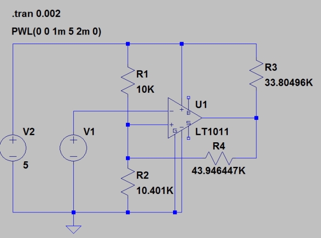
Figure 3 shows a schematic for a Schmitt trigger circuit using an open-drain comparator.

Figure 3: Schmitt Trigger Circuit Using Open Collector Comparator.

Figure 3: Schmitt Trigger Circuit Using Open Collector Comparator.

Calculations

My calculation objective is create formulas for each of the resistors in the circuit as a function of the my critical voltage specifications, which are {{V}_{TH\uparrow }}, {{V}_{TH\downarrow }}, {{V}_{H}}, {{V}_{L}}, and {{V}_{CC}}.

Because there are so many variables (5), I have chosen to normalize my calculations. In this case, I will express all the voltages relative to VCC and all resistors relative to R1. This reduces the number variables down to three, which is more manageable. My graduate school adviser, Aram Budak, would always chastise me when I carried around unnormalized variables in my calculations. He said the extra work was simply not worth it, and he was right. For those who want to see a more conventional derivation, see my response to a question at the bottom of the post.

I begin my calculations by expressing R4 in terms of my voltage specifications (see Figure 4).

Figure 4: Normalized High Output Voltage Equation.

Figure 4: Normalized High Output Voltage Equation.

In Figure 5, I now setup a system of equations that will give me the equations that I need to compute my normalized resistor values.

Figure 5: Solution to the Normalized Resistor Equations.

Figure 5: Solution to the Normalized Resistor Equations.

Figure 6 shows a worked example. Notice how I normalize all the voltages before I insert them into my formulas and then I need to unnormalize the results.

Figure 6: Worked Example.

Figure 6: Worked Example.

Simulation

Before I build a circuit, I always like to simulate it. Here are my LTSpice results for this circuit.

Schematic

Figure 7 shows the circuit I simulated.

Figure 7: LTSpice Schematic.

Figure 7: LTSpice Schematic.

Simulation

Figure 8 shows my simulation results. My critical voltages are exactly what I wanted because my equations allowed me to model the finite output voltage of the comparator when in the "low" state (~0.152 V).

Figure 8: LTSpice Results.

Figure 8: LTSpice Results.

Conclusion

In this blog post I designed a simple Schmitt trigger circuit for use in a home project. As part of this effort, I was able to derive equations for the associated resistor values in terms of the normalized transition and output voltages. My equations allow me to account for the non-zero output voltage of the comparator when it is in the "low" state. I simulated the circuit using LTSpice and I showed that it worked as I expected.

Save

Save

Save

Save

Save

Posted in Electronics | 14 Comments

Old School Spacecraft Thermal Insulation

Quote of the Day

Everything not forbidden is compulsory.

— T.H. White, The Book of Merlin. I have heard people make similar statements about quantum mechanics, particle physics, and cosmology.


Introduction

I saw this article about a solar probe called the Solar Orbiter that uses a form of insulation with a history that dates back to early man. The article makes the following statement.

At such a close distance, the spacecraft needs protection from the sun's powerful rays. The mission will endure 13 times the intensity of normal sunlight and temperatures as high as 520°C.

I will show where the factor of 13 comes from. Before I discuss the insulation, however, here is a brief video that describes the mission of this probe.

Background

The article describes the insulation as a pigment similar to that used to make cave paintings by ancient man.

The pigment is called 'Solar Black', a type of black calcium phosphate processed from burnt bone charcoal. It retains its properties under intense conditions, even over thousands of years.

The material was developed by the Irish company Enbio.

Analysis

The article states that the probe will come as close as 42 million kilometers to the Sun. Since radiation intensity follows an inverse-square law relationship with distance, we can compute the increase in solar intensity with distance shown in Figure 1.

Figure 1: Increase in Solar Intensity with Distance.

Figure 1: Increase in Solar Intensity with Distance.

Conclusion

I was able to derive the stated 13x increase in solar radiation level using a simple square-law relationship.

I find the use of low-tech materials and techniques interesting in high technology projects. Other examples I have seen recently include:

Posted in Astronomy, History of Science and Technology | 1 Comment

Mars Rover Solar Panels Getting Dirty

While reading some articles on the Mars rovers, I saw this pair of pictures showing the Opportunity rover's solar panels first deployed in January 2004 and today − its solar panels are now very dirty (Source). There was a time when NASA would talk about cleaning events -- winds that would clear the panels. I do not hear much about cleaning events anymore.

Figure 1: NASA Images of Clean and Dusty Solar Panels.

The dust has produced a remarkable reduction in daily energy output (Source).

As of Wednesday, Jan. 15, 2014, or Sol 3547, the solar array energy production on the rover is 353 watt-hours, compared to 900 watt-hours after landing.

Even though the daily energy output is less than 40% of its original value, the rover is continuing to do good work.

The Curiosity rover uses two nuclear batteries and it does not have the same sensitivity to dust as the Opportunity and Spirit rovers.

Posted in Astronomy | Comments Off on Mars Rover Solar Panels Getting Dirty