Quote of the Day
Ability is of little account without opportunity
— Napoleon Bonaparte
Introduction
I was asked a question today about how to design a two-resistor thermistor linearization circuit. This very brief post is intended to provide the background needed for this task.
Background
Scope
There are numerous ways that one can linearize a thermistor's temperature response. In this case, I put the thermistor into a voltage divider and select resistor values that will produce a transfer function with a zero second-derivative at a point I select. The zero-second derivative means that the curve is linear at the point I chose.This work is a straight-forward generalization of the one-resistor linearizer as covered in this blog post. I like this approach because:
- I can select the point about which I have maximum linearity.
My applications usually need high accuracy within a certain temperature range and less accuracy outside of this range. This approach allows me to move the temperature interval of maximum linearity to where I need it.
- The approach is computationally simple.
Two resistors values to compute -- two formulas. Doesn't get much simpler than that.
Compared to the one-resistor linearizer in this post, the two-resistor linearizer gives you wider dynamic range at the cost of lower sensitivity and adding another part. Like all engineering tradeoffs, you have to decide what you need.
Derivations
The derivations were a tad long and I used a computer algebra system to perform them (Mathcad). Appendix A contains the details. You will not see all the intermediate steps because Mathcad will perform many simplifications in each step.
Analysis
This is an arbitrary example I made up to illustrate the process.
Thermistor
Figure 1 shows a thermistor that I am familiar with and I will use in this example (datasheet).
Circuit
Figure 2 shows the two-resistor linearizer. Nothing special here.
Equation Definitions
I will be linearizing the divider ratio of the thermistor with the two resistors. I will define this ratio as shown in Figure 3.
Modeling
Figure 4 shows how I modeled the problem mathematically. My basic approach was to:
- Set the second-derivative of the gain curve to zero at a temperature I call the inflection temperature TI. The engineer can choose TI.
- The engineer chooses the desired resistor ratio at TI,
. Not all ratios are possible for a given thermistor. Ratios less than
result in negative RP values.
- μ is used to compute RS using the formula
.
- Knowing RS allows me to compute RP using the formula
.
This finishes the calculation. The raw Mathcad file can be obtained here. It is an XML file, so download it to your computer and read it into Mathcad. Your browser will just show you text. I have also included an Excel worksheet.
Graph Setup
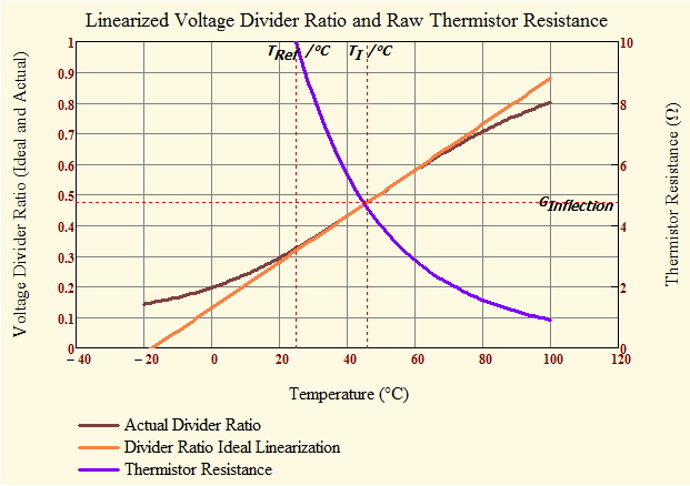
Figure 5 shows how I setup my graph of the resistor divider output versus a straight line with the same slope at the temperature TI.
Graph
Figure 6 shows my graph of the thermistor's divider ratio and compares it to that of a straight line with the same slope as the resistor circuit at TI.
Conclusion
I wish I had more time to work on the discussion portion of this post. I am hoping the derivations presented are sufficiently detailed for folks to follow.
Appendix A: Derivation of RP and RS Formulas
Figure 7 shows my Mathcad derivation for the key formulas in this post. I am basically lazy and I let the software do all the simplification. I love math, but hate algebra.


Thanks, very usefull.
I had to write this post quickly. I will try to improve it over time.
Mathscinotes
Thanks for the worksheet!