Quote of the Day
Good intentions will never take you anywhere you want to go. Only intentional living will get you the things you want in life.
- John C. Maxwell
Introduction
A big part of my job revolves around cables so it's fair to say that I have a lot of knowledge about them. Whether it's using wrap around cable labels to make maintenance easier or replacing broken cables or informing customers about basic cable management. Why am I telling you this? Because I am preparing some customer education material on coaxial cables for customers (Figure 1 shows some coaxial cable examples) and I thought this information was worth documenting here. Our fiber optic products interface to coaxial cables so that service providers can use existing in-home wiring. If you are looking for a cable supplier, you can check out Sava who has a wide range of various cable types, that can be used for differing electrical needs.
Coaxial cable is much more commonly used in the United States for residential interconnect than in the rest of the world -- about 90% of US homes have coaxial cable already wired within them. In my opinion, it is also the most misunderstood of the broadband interconnection products. However, not all homeowners are aware of all of their options when it comes to cable. In fact, many end up saying things like 'I only thought there were a few cable providers in my area' when there is actually a lot more than you'd think. That is why it is always wise to shop around before committing to one particular provider.
My intent here is to cover some of the basic math associated with two important coaxial cable parameters. In later posts, I will discuss how the temperature affects coaxial cable losses and length, which are the specific topics that I am addressing with customers this week.
Background
Construction of Coaxial Cable
Figure 2 shows a section drawing of coaxial cable.
Figure 3 nicely shows how a typical coaxial cable is constructed (RG-59 in this case). RG-59 and RG-6 cables are very similar. RG-59 is cheaper and media equipment manufacturer's (e.g. like for TV and DVD players) often include it with their gear for use with short interconnections because it is cheaper than RG-6. RG-6 has a heavier core conductor and better shielding, so it works better for longer runs.

Figure 3: RG-59 Coaxial Cable Components: (A) Outer plastic sheath, (B) Copper braid shield, (C) Inner dielectric insulator, and (D) Copper or copper-plated core (Source: Wikipedia).
Types of Coaxial Cable
Here is a good article on some common types of coaxial cable. However, this post will focus on RG-6, which is commonly used in residential analog video deployments (e.g. NTSC). My questions from the field are nearly always about RG-6 cable. As analog video vanishes, the in-place coaxial cable is being re-purposed to carrying digital video using MoCA and HPNA. So we are going to see the residential use of coaxial cable for a long time.
History of Coaxial Cable Impedance Values
I found some interesting articles that discussed the history of 50 ? and 75 ? characteristic impedance values for coaxial cables:
- Definitive web-based article.
- Very good forum discussion on the choice of impedances.
- Mentions common plumbing sizes as setting impedance values.
- Sober discussion on the difficulty of matching impedances.
Analysis
From my standpoint, the two most important electrical characteristics of coaxial cable are:
- Characteristic Impedance
- Attenuation
I will use a couple of common formulas for estimating these values using two different types of RG-6 cables. I will not attempt a derivation because the good folks at Microwaves101 have done a great job documenting the formulas for both characteristic impedance and attenuation.
Characteristic Impedance
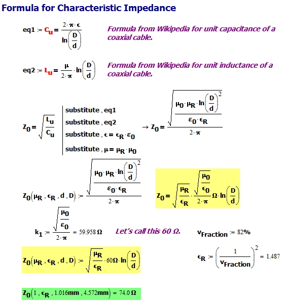
Figure 4 shows how the mechanical construction of an RG-6 cable determines its characteristic impedance. For my example cable, I used the Belden 1694A. Figure 4 assumes that µR = 1, which is true for most non-ferrous materials (link).
My calculations show a 74 ? characteristic impedance for this cable, which is very close to the manufacturer's stated 75 ?.
Attenuation
Figure 5 shows how the mechanical construction, length, and frequency of use of an RG-6 cable (again, Belden 1694A) determines its attenuation. My result shows an error of 9.5%, which does not surprise me because this formula does not model dielectric loss. This can be modeled, but I do not want to go into these details for training newbies.
Conclusion
This was just a quick note to document how two key coaxial cable parameters are computed. I decided to document these calculations because I saw them done incorrectly in some forum discussions.
The key problem that folks were having was determining the relative permittivity of the dielectric material. Most of the coaxial cable today use dielectrics that have tiny gas bubbles in them. This reduces their effective relative permittivity. The erroneous calculations that I saw were using the relative permittivity of solid dielectric material with no injected gas.


Pingback: Untilting RF Video Signals | Math Encounters Blog
in here uR (relative permeability) how do you take as 1 ??
Hi Thilinia,
The most common dielectric material in coaxial cable is PTFE (reference). The magnetic permeability of PTFE (and all the other plastics that I know of) is very near 1. This is discussed in this reference from which I quote.