Market Analysis Math

Introduction

One of the roles that an engineering manager has to occasionally play is advocate for a product that you believe in. Every successful product that I can think of began with some individual who was an internal advocate, a role which is sometimes referred to as a product champion. This advocacy frequently requires that you perform some market analysis. I believe that market analysis is key to developing products that address customer needs. The best product designs tend to strike the right balance between cost, features, and time to market. Setting this balance requires market information.

Some companies may use/develop software to better understand their customer base, this could be using software like advance gaze data analysis. This type of technology can help companies/researchers better understand what the customer's needs are and what they go for by analyzing where they look and what they zone in on mostly. It is something that has become more advanced in years and can be looked at as a precise marketing tool. Coupled with the right Excel plugin for conjoint analysis, most modern marketers will have unparalleled insight into their customer's preferences.

Investing in the markets is something which more and more people are becoming interested in. From the stock market to cryptocurrency, individuals can find advice, like this ber Bitcoin Bank berichtet (report on Bitcoin Bank), online about investing. However, when it comes to market investment, not many people understand the basic mathematics that is involved.

Gathering mathematical information requires some digging. The mathematics is pretty simple (adding and subtracting), but is nonetheless important. I thought I would document some recent work to show you how I go about it.

Market Analysis Example

I cannot go into the exact details of the product that I am championing, but I can say the following:

  • I need to understand the percentage of people that live in homes (broken down as detached or attached homes -- attached homes are row houses) or apartments (often referred to as multi-dwelling structures)
  • I need to understand how these percentage vary by region of the US or by country in Europe.

It turns out that this information is readily obtainable from web sites that specialize in demographic data:

  • US Census Bureau
    This place has an amazing amount of information of all sorts. We will focus on the housing information.
  • Eurostat
    This site also has a lot of country-specific information.

This data helps provide us into several critical product development factors:

  • Total Addressable Market (TAM)

    For businesses and investors, calculating total addressable market is a crucial part of their success. TAM is important because the market must be large enough to provide the required Return on Investment (ROI).

  • Feature Mix

    Successful product development usually deals with issues that I call "Goldilocks Problems." Goldilocks wanted porridge at just the right temperature. Successful products solve just the right problems. They solve the problems of enough people at the right price that you will sell enough product to make money. Solving all the problems of all the people tends to result in products that nobody can afford.

  • Geographic Locations to Focus On

    Just like you would not want to sell snow-making machines to someone who lives in the arctic, you want to focus your sales efforts where the buying customers are.

Results

It was surprising easy to find the data that I needed. The census data was downloaded as Excel files. I threw the data into a pivot tables and generated the following plots.

US Data

Figure 1 illustrates the mix of housing in the US by region.

Figure 1: Mix of US Residential Housing By Region.

Figure 1: Mix of US Residential Housing By Region.


Figure 2 illustrates the size distribution of multi-dwelling units in the US.
Figure 2: Size of Multi-Dwelling Units in the US.

Figure 2: Size of Multi-Dwelling Units in the US.


This data will help me answer questions like:

  • Should we focus on single-family homes or apartments?

    Single-family homes have different packaging and powering requirements from apartments. We need to know which type of residence we are targeting in order to get a solution that is easy to deploy.

  • What is the mix of services required?

    Fiber to the home customers need voice, video, and data services. Providing ports for these services is a major cost driver. To make money, we need to sell enough products to justify the development cost. To sell enough products, we need to provide enough ports to ensure we meet the needs of the bulk of the customers.

  • Where are the customers for our products?

    We want to focus our sales efforts where the customers are.

  • International Data

    Figure 3 shows the residential housing mix for a number of European nations.

    Figure 3: European Residential House Mix.

    Figure 3: European Residential House Mix.


    Figure 4 shows the mix of MDU sizes for a number of European nations.
    Figure 4: Size of European MDU Units.

    Figure 4: Size of European MDU Units.

    Conclusion

    Sometimes product development requires looking at customer requirements in order to define the correct product. Often the numbers are difficult to acquire. In this case, I found the numbers I was looking from European and American census data. It was a simple, effective, and free way to get product information.

Posted in Management | Comments Off on Market Analysis Math

Spare Parts Math

Introduction

I received a phone call from a panicked account manager at our headquarters last Thursday. A proposal needed to go out Friday and the proposal team did not have all the information that a customer had requested. The account manager needed reliability data on our products and an estimate on the number of spare parts that the customer would need to keep on hand for servicing their deployment. They needed an answer fast (< 24 hours). Normally, an engineer from our Quality department would answer these questions. Unfortunately, the engineer responsible for this work was on vacation and could not be reached. The question eventually came to me because I have worked on similar problems in the past. Could I help? Here is how I proceeded to answer the questions.

Problem Statement

Let's frame the problem a bit more precisely. The customer has requested the following information:

  • Estimates of the Mean Time Between Failures (MTBF) data for the optical products that this customer was going to purchase.

    There is a standardized way to estimate these numbers. I don't agree with the standard, but that is beside the point.

  • MTBF estimates for products from other supplies that are used with our equipment.

    This is basically an information gathering task plus a little bit of algebra.

  • Estimates for the number of spare parts required to be kept on hand to provide a 95% confidence level that the customer would have adequate spares on hand.

    This customer only replenished his spares once a quarter and wanted ensure that they had adequate quantities on hand.

Analysis

Let's take the questions on one at time.

MTBF Estimates for Our Products

The customer had asked for reliability estimates based on an industry standard, specifically Telcordia's SR332. This approach is straightforward:

  • Obtain estimates for the MTBF of each part used in each product.

    These estimates are available from the vendor for each part. The vendors often do not like to give you the MTBF estimate because they do not want the estimate to imply a warranty of operational life, but they all have the estimate.

  • Combine these estimates using MTBF_{Assembly}={}^{1}\!\!\diagup\!\!{}_{\sum\limits_{i=1}^{N}{\frac{1}{MTBF_i}}}

    MTBFAssembly is the MTBF of the entire assembly, MTBFi is the MTBF of the ith component in the assembly, and N is the number of components in the assembly.

This approach produces what is called a "parts count" MTBF estimate. It assumes that an assembly's failure rate is dominated by random part failures. It turns out that all these calculations were already performed and were in our document control system. The folks at headquarters did not know where to look for the data. So I sent them an email with a table summarizing the data.

I mentioned earlier that I do not agree with this approach to estimating MTBF. In my experience, I have seen little correlation between the MTBF estimate using the parts count method and actual field failure rates. The reason is simple -- field failures are primarily due to factors that have nothing to do with random part failures. For example, lightning is the single largest cause of field failures that we encounter. The part count MTBF estimate does not model lightning failures. If I were king of the world, I would estimate spare parts requirements using the regional field failure rates. This number is usually about 0.1 % of the installed based per year, but varies by the level of lightning strikes and average temperature.

Lightning severity and frequency varies by geographic region. For the US, it is worst in the Gulf Coast region, especially Florida. Where do we see the highest product failure rates? The Gulf Coast region, with Florida being the worst.

MTBF Estimates for Other Components

Unfortunately, gathering this information was a bit of a problem. If a part vendor had provided an MTBF estimate, I used it. However, not all vendors provided this information. Since I only had a small a few hours, I decided to work by analogy. There is actually little difference in the computed reliability of the parts from different vendors - we all use similar parts from similar vendors. For each part that did not have a stated MTBF, I found a comparable part that did have a specified MTBF and I used that for my analysis.

Once I had all the MTBF values, I could create a table with MTBF values for each part that the customer would be using. I will use this table to create an estimate of the spare parts inventory requirements.

Spare Parts Requirements

There was some serious math to be done here. The following assumptions here are reasonable for the products under consideration by this customer:

    • The products fail and cannot be repaired.

      This certainly is true for lightning failures. The term "lightning failure" really does not due justice to what happens. Frequently the electronics are destroyed. Other types of failures can be repaired, but it may not be economically worth it. In many cases, it is cheaper to just replace the failed item.

    • We can model the failure rate using a Poisson probability distribution.

      You have to assume some distribution and the Poisson is a analytically tractable.

    • The inventory of spare parts is replenished at regular intervals.

      This is because companies tend to periodically perform inventory checks and replenish their inventories when they see their stocks are low.

    • The customer wants a 95% confidence that his spare inventory will be adequate.

      This is a common assumption. You normally see confidence levels of 90%, 95%, or 99%.

    • The customer wanted us to use our MTBF prediction from the parts count method.

      We have real field data, but the customer wanted us to use the MTBF prediction by the part count method. I salute smartly and use that estimate.

We can use Equation 1 to compute probability of using a given number of spares, PSpares(s), during an interval of time. Equation 1 simply sums the Poisson probabilities of using different numbers of spares.

Eq. 1 {{P}_{Spares}}\left( s \right)=\sum\limits_{k=0}^{s}{\frac{{{\left( N \cdot \lambda \cdot T_R \right)}^{k}}}{k!}}\cdot {{e}^{-N \cdot \lambda \cdot T_R}}

where

      • PSpares(s) is the probability of using s spares.
      • s is the largest number of spares allowed.
      • N is number of assemblies deployed
      • k is an index variable for the number of spares used.
      • λ is failure rate of the assembly, \lambda ={}^{1}\!\!\diagup\!\!{}_{MTBF}\;.
      • TRis the replenishment time.

        The replenishment time varies by customer. In this case, TR=3 months

My plan is to use Mathcad to solve for the number of spares s that I require to meet the 95% reliability requirement. You can see this calculation in Figure 1.

Figure 1: Mathcad Routine for Computing Required Spares.

Figure 1: Mathcad Routine for Computing Required Spares.

While Figure 1 shows an exact calculation, the Normal distribution can be used to approximate the Poisson distribution when N\cdot \lambda \cdot t>10, which is true in this case. Equation 2 shows how to compute the Normal approximation to the Poisson calculation of Figure 1.

Eq. 2 s=N\cdot \lambda \cdot {{T}_{R}}+{{k}_{CL}}\cdot \sqrt{N\cdot \lambda \cdot {{T}_{R}}}

where kCL is a constant corresponding to the confidence level desired. For a 95% confidence interval, we observe that N(1.645,\mu ,\sigma )=0.95. Thus, {{\left. {{k}_{CL}} \right|}_{CL=95\%}}=1.645.

We illustrate the results of this calculation in Figure 2. The results obtained from the approximation are almost identical to those of Figure 1.

Figure 2: Illustration of Normal Approximation to the Poisson Distribution.

Figure 2: Illustration of Normal Approximation to the Poisson Distribution.

Conclusion

Catastrophe averted. It was a nice illustration of the use of the Poisson distribution for a real-world problem. It also shows how a well planned day can be upset with a single phone call.

Addendum

I have had a request for an Excel version of this calculation. I have included two tabs:

  • array formula-based, which provides a very short solution in Excel 2010
  • data table-based, which works for Excel 2003

Spare Parts Example in Excel

I have also been asked to make a version available that does not use named variables. Here you go.

NoNamesExcelFile

I have also been asked to make my Mathcad 15 worksheet available. Here you go.

Mathcad Version
Just save the file to your computer and load it into Mathcad. Your browser will try to view it as an XML file.

There is a Mathcad Prime 2.0 version as well. Here is a sheet for that version.
Mathcad Version

Posted in Electronics | 96 Comments

Lunch Time Math

I received a comment the other day in reference to a previous blog post on World War II torpedoes and submarines. I was asked if I could go into more detail about how the fire control problem was solved. I had some time over lunch today, so I wrote a quick description. As I wrote up my answer, I thought it might be interesting for people to see how I write up my mathematics for commercial use. I cannot post my business correspondence because of confidentiality issues, but I used the same format for this document.

Anyway, I was asked to provide information on how to implement the algorithm described in this old US Navy reference -- downloaded from HNSA's excellent web site.

Excerpt from Old Navy Torpedo Data Computer Manual

I put together a Mathcad model that worked nicely for this application. Since most folks do not have Mathcad, I PDFed the worksheet and put it here.

Position Keeper Modeling

Posted in History of Science and Technology, Technical Writing | 4 Comments

Beamforming Math

Quote of the Day

A satisfied customer is the best business strategy of all.

— Michael LeBoeuf, writer and management professor.


Introduction

Figure 1: People Seem to Love More External Antennas.

Figure 1: Multiple antenna elements makes beamforming possible. (Source)

I was at the Consumer Electronics Show (CES) last week and spent a lot of time talking to various silicon vendors about their wireless offerings. During these discussions, the topic of beamforming came up numerous times. Beamforming maximizes the transmit energy and receive sensitivity of an antenna in a specific direction. Beamforming is becoming a critical technology for improving the data transfer rate of wireless systems -- rates that are critical to making wireless technology a credible option for delivering reliable Internet Protocol (IP) video around a home. The reliable delivery of IP video over wireless will simplify the deployment of Fiber-to-the-Home systems (my focus) by eliminating the need to install Ethernet cables to every room, which is expensive.

These discussions brought back many memories. Years ago, I spent a lot of time working on beamforming for military sonar and radar systems. Military and aerospace technology often finds a home in commercial applications once it becomes cost effective, and beamforming is now becoming inexpensive enough to be in every home. Because I was familiar with the technology, I decided that it would be worthwhile to put together some training material for my staff on how beamforming works. I began by writing a Mathcad worksheet for simulating a simple linear antenna array. This simulation seemed to be a good way to illustrate how beamforming works and I thought it would be worthwhile to cover here.

Background

Let's begin by defining beamforming. As usual, let's turn to the Wikipedia.

Beamforming is a signal processing technique used in sensor arrays for directional signal transmission or reception. This is achieved by combining elements in the array in a way where signals at particular angles experience constructive interference and while others experience destructive interference. Beamforming can be used at both the transmitting and receiving ends in order to achieve spatial selectivity. The improvement compared with an omnidirectional reception/transmission is known as the receive/transmit gain (or loss).

I really like this definition because it focuses on the critical role of interference in allowing us to either direct energy (acoustic or electromagnetic) in a desired direction or to receive energy from a desired direction. Using advanced methods, we can also reject sending or receiving energy from a specific direction, which is called null steering. Beamforming will be my focus here.

Beamforming is useful for wireless communication because these systems have limited transmit power and it is best to point the energy you transmit toward an actual receiver. When you are receiving, it is best to listen carefully in the direction of a transmitter and to reject noise coming from other directions. Null steering is useful when you have source of interference that you wish to reject, which could be something as common as a microwave oven making popcorn or a neighbor's wireless system.

Since beamforming is a such a good thing to do, let's now take a closer look at how it works.

Analysis

All mathematics going forward are done using complex numbers.

Reciprocity

As mentioned above, beamforming can be applied to both transmitting and receiving. In fact, transmit and receive beamforming are identical because of the principle of reciprocity, which states that the receive sensitivity of an antenna as a function of direction is the same as the transmit radiation pattern from the same antenna when transmitting. See the Wikipedia for a discussion of this topic.

Linear Antenna Array

For the purposes of this post, I will use the simple model of a linear array shown in Figure 1.
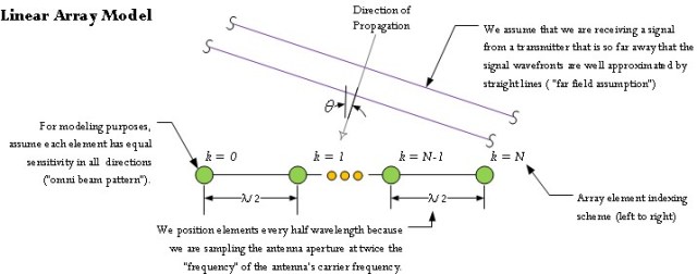
Figure 1: Linear Antenna Model.

Figure 1: Linear Antenna Model.

To keep this discussion simple, I will make the following assumptions:

  • The antenna is composed of a series of identical elements separated by λ/2, where λ= c/f, c is the speed of light, and f is the frequency of transmission.

    Since the dawn of radio, engineers have been directing radio power along specific directions using shaped reflectors (e.g. parabolas). You can analyze antenna arrays using the viewpoint that we are sampling these apertures using small antennas that I will refer to here as elements. Since we are sampling an aperture, λ/2 makes sense because it corresponds to the Nyquist sampling rate for a receiver with a wavelength of λ. I will not be taking a sampling viewpoint for the remainder of this post, but I may in future posts.

  • Every element is a receiver -- I will ignore transmitting.

    By the reciprocity theorem, everything I say for a receiving antenna will also be true for a transmitting antenna. I am making this assumption just to reduce the amount of redundancy in this discussion. You should think of every element as a small antenna. We are going to be working with arrays of small antennas.

  • The receiver elements generate an output voltage or current that is proportional to the level of the signal impinging upon it.

    This means that that output of an antenna element is an accurate reproduction of the signal strength impinging upon it.

  • Every element has an omnidirectional sensitivity response.

    This means that every element is equally sensitive in all directions.

  • Assume that the wavelength λ = 1.

    Expressing all lengths in units of λ does not limit this discussion in any way and is simpler to deal with analytically. This means that the elements are separated by 1/2 in units of λ.

Given these assumptions, we can now create a mathematical model for the receive output of a linear array as a function of beam angle. While the linear array example is simple to analyze, it does illustrate the basic approach to analyzing larger and more complex antenna arrays.

Simple Beamforming Algorithm

What is Beamforming Computationally?

Beamforming computationally is simply the linear combination of the outputs of the elements, which a beam can be computed using Equation 1.

Eq. 1 \displaystyle \zeta \left( \theta \right)=\sum\limits_{k=0}^{k=N}{{{a}_{k}}\left( \theta \right)\cdot {{x}_{k}}}

where

  • N is number of elements.
  • k is an index variable.
  • ak is the complex coefficient of the kth element.
  • xk is the voltage response from the kth element.
  • ζ is the beam response.
  • θ is the angle of the beam main lobe.

Equation 1 is not difficult to compute, but we need to determine what coefficients we should use to enhance the antenna's receive gain in a specified direction. The mathematics behind computing these coefficients is covered below.

Intuitive View of Array Beamforming

Consider Figure 2, where we have a transmitter that is far away from our linear antenna. "Far away" in this case means that the transmitter is many wavelengths distant from the receiving antenna.

Figure 2: Illustration of the Phase Shift At Each Element.

Figure 2: Illustration of the Phase Shift At Each Element.

For a transmitter that is far enough away, the wavefronts can be approximated as plane waves when they arrive at the receive antenna. When we evaluate Equation 1 for the situation shown in Figure 2 assuming that ak=1 , the maximum response is generated when all wavefronts hit each element at the same time (perfect constructive interference). This will occur when the transmitter is located on a line that is perpendicular to the orientation of the linear array. If the transmitter moves away from the perpendicular, destructive interference begins to occur and the magnitude of the response reduces.

In order to steer the beam in different directions, we need to look closely at Figure 2 and observe that, for transmitters that are not along the perpendicular, there is a linearly increasing phase shift introduced along the array elements. Can we use the coefficients to cancel out the phase differences and rotate the direction of maximum antenna response? It turns out we can.

We can compute the phase shift in the signal received between each element using Equation 2. The key to deriving this equation is to note that each element receives the same signal, but at a slightly different time. This time delay can be modeled as a phase shift in the frequency domain.

Eq. 2 y\left( t \right)=\sin \left( 2\cdot \pi \cdot f\cdot \left( t+\delta t \right) \right)=\sin \left( 2\cdot \pi \cdot f\cdot t+\varphi \right)
\varphi =2\cdot \pi \cdot f\cdot \delta t
\sin \left( \theta \right)=\frac{c\cdot \delta t}{\frac{\lambda }{2}}=\frac{\frac{c\cdot \varphi }{2\cdot \pi \cdot f}}{\frac{\lambda }{2}}=\frac{c\cdot \varphi }{\pi \cdot f\cdot \lambda }=\frac{c\cdot \varphi }{\pi \cdot c}=\frac{\varphi }{\pi }
\therefore \quad \varphi =\pi \cdot \sin \left( \theta \right)

where

  • θ is the angle of target relative to a vector normal to the center of the element array.
  • φ is the phase shift between each element.
  • δt is the time delay of the signal between the elements.
  • f is the transmit frequency.
  • c is the speed of light.
  • t is time.

If we can compensate for the phase shift, we can maximize our receiver's response in the direction of the transmitter. That is exactly what we are going to do.

Beamforming Simulation

Here is the approach I am going to use to determine the output of a simple beamformer.

  • Determine the distance from each element to the source using the Pythagorean theorem.
  • Determine the amplitude and phase of the signal at each element using the distance.
  • Evaluate Equation 1.
  • Plot the output of Equation 1 as a function of transmitter angle.

Distance to the Transmitter

Equation 3 shows my Mathcad program for generating the distance between an element and the transmitter.

Eq. 3

where

  • N is number of elements.
  • r is the radial distance to the transmitter.
  • θ is the angle of target relative to a vector normal to the center of the element array.
  • k is the element index (labeled from left to right in Figure 1).

Amplitude and Phase of the Received Signal

Equation 4 gives the phase of the signal at element as a function of distance. This formula uses the fact that each wavelength of distance equals 2·π of phase.

Eq. 4 \varphi ={{\left. \frac{\text{dist}\left( k,\theta ,r,N \right)}{\lambda } \right|}_{\lambda =1}}\cdot 2\cdot \pi =\text{dist}\left( k,\theta ,r,N \right)\cdot 2\cdot \pi

Evaluate Equation 1

My approach to evaluating Equation 1 is to break it into three parts.

  • Generate a vector of steering coefficients.
  • Compute a matrix of the element responses over a range of transmitter angles.
  • Form the matrix product of the steering coefficients and the element responses, which is equivalent to evaluating Equation 1.

Figure 3 illustrates how I compute the compensating phase shifts for two different beams. It turns out that you can generate multiple beams in parallel and I will illustrate below.

Figure 3: Generate the Coefficients For Generating a Beam in A Specific Direction.

Figure 3: Generate the Coefficients For Generating a Beam in A Specific Direction.

Figure 4 illustrates how to compute a matrix of element responses for a transmitter positioned along a range of angles from 0° to 180°.

Figure 4: Element Responses for a Range of Angles from 0° to 180°.

Figure 4: Element Responses for a Range of Angles from 0° to 180°.

Plot the Output of Equation 1

Figure 5 shows a plot of sensitivity for two beams, at 45° and -30° off the perpendicular (b1 contains the coefficients for 45° and b2 contains the coefficients for -30°).

Figure 5: Two Beam Patterns for an 7 Element Antenna and a Transmitter at Range = 1000 λ.

Figure 5: Two Beam Patterns for a 7 Element Antenna and a Transmitter at Range = 1000 λ.

Conclusion

There is a lot more to talk about here, but I was able to put together a simple beamforming example for my team. You can see from this example that one can "point" the response curve of the antenna in specific direction with just a bit of matrix math. Note that the antenna beam patterns have a main "lobe" and side "lobes." In a later post, I will discuss how to reduce the amplitude of the sidelobes.

Save

Save

Posted in Electronics | Tagged , , | 12 Comments

Approximation Math

Introduction

Back in 2003, I used an approximation for the logarithm function in a hardware application. When originally implemented, the function only had to work for a limited range of input. Recently, a customer has requested that we expand the range of operation for this function. This post examines how I went about expanding this approximation's range of operation.

Engineers frequently have to approximate common mathematical functions. You might wonder why we still need to approximate these functions when there are excellent mathematical libraries available for all commonly used processors. There are two reasons:

  • Speed
    Library functions are coded for accuracy and they frequently take a long time to execute. There are applications where accuracy is less important than speed and approximations may accurate enough and fast enough to solve your problem. For example, I have had to use approximations to the square root function when computing the magnitude of vectors in real-time navigation applications. Library functions simply were too slow.
  • Cost
    Library functions require lots of memory and may force you to buy a faster processor in order to execute them. My cost limitations are usually so tough that I have to use cheap processors like AVRs, which have limited memory and throughput. I need to find inexpensive ways to implement math functions on these brain-dead computers.

We will examine my original implementation and how I went about expanding its range of operation, which engineers refer to as the function's "dynamic range."

Background

Decibel Basics

Technically, I view decibels as a scaling rather than a unit. Decibels are always expressed relative to a unit, in this case milliwatts. Equation 1 defines the dBm, which means decibels relative to one mW.

Eq. 1 {{P}_{dBm}}=10\cdot \log \left( {{P}_{mW}} \right)

where

  • PmW is the measured power in milliwatts [mW],
  • PdBm is the measured power expressed in decibels milliwatt (dBm)

I need to approximate Equation 1 over a range from - 6 dBm to 0 dBm with an accuracy of better than 0.5 dB. This post will use a 4th-order polynomial to approximate the logarithm function. Equation 2 defines my polynomial model. I also include an equivalent matrix version.

Eq. 2 d{{B}_{Approx}}(x)={{a}_{4}}\cdot {{x}^{4}}+{{a}_{3}}\cdot {{x}^{3}}+{{a}_{2}}\cdot {{x}^{2}}+{{a}_{1}}\cdot x+{{a}_{0}}
d{{B}_{Approx}}(x)=\left[ {{a}_{4}}\quad {{a}_{3}}\quad {{a}_{2}}\quad {{a}_{1}}\quad {{a}_{0}} \right]\cdot {{\left[ {{x}^{4}}\quad {{x}^{3}}\quad {{x}^{2}}\quad x\quad 1 \right]}^{T}}

Now that we know a bit about decibels, let's discuss how cable TV works, and if you want some more information, you can also click here to check out the updated cable TV statistics for this year.

Some Cable TV Basics

Figure 1 illustrates the scenario I find myself in. In general, one laser will drive multiple stages of amplification. Thus, one laser and a "tree" of EDFAs can serve thousands of homes.

Figure 1: General Optical Deployment Model using Lasers and EDFAs.

Figure 1: General Optical Deployment Model using Lasers and EDFAs.


Video service providers use a laser to transmit their video signal to the homes they serve. The power of this signal is important because it determines how many homes can be served -- every home must receive a specified level of power to provide a high quality signal. However, more optical power requires more expensive transmission gear (e.g. devices called EDFAs). Service providers want to use exactly the amount of optical power that they need and no more. They set the power of this signal in decibels because that is how the equipment was designed (again, the decibel legacy). For all sorts of reasons, my gear at the home needs to measure the power of this signal. However, real components measure power in mW (or a similar unit) not decibels. Yet, I need to be able to provide an optical power measurement in decibels for system monitoring purposes. I do not want to raise my product costs by adding memory just to compute decibels. So I decided to use a polynomial approximation to the logarithm because it requires little memory and is very fast on an AVR processor.

Analysis

My Original Polynomial Approximation

Figure 2 shows my Mathcad implementation of a minimum-maximum error curve fit routine. I chose to use a dynamic range from -6 dBm to 0 dBm (to be truthful, the actual range I used was slightly different but for reasons that are unimportant here).

Figure 2: My Original Determination of Logarithmic Approximation Coefficients.

Figure 2: My Original Determination of Logarithmic Approximation Coefficients.


Figure 3 shows the "goodness of fit" for this approxmation.
Figure 3: Goodness of Fit for the Original Approximation.

Figure 3: Goodness of Fit for the Original Approximation.

A Wider Dynamic Range Version

Approach

A service provider wants me to expand the range of operation of my optical power measurement to -12 dB to 6 dBm from -6 dBm to 0 dBm. As I thought about it, I made the following observations.

  • I can break this range into three parts related by a factor of 4:
    • -12 dBm to -6 dBm
    • -6 dBm to 0 dBm
    • 0 dm to 6 dBm
  • You can see these ranges are related by a factor of 4 by noting that 10\cdot \log (4)\doteq 6 \text{ dB}

Given these observations, I can state Equation 3.

Eq. 3 10\cdot \log \left( 4\cdot x \right)=10\cdot \log \left( x \right)+6
10\cdot \log \left( \frac{x}{4} \right)=10\cdot \log \left( x \right)-6

So I can use my dB approximation over a wider dynamic range by using Equation 3 as shown in Equation 4.

Eq. 4

Results

Figure 4 shows the effectiveness of my approximation. This is not too bad and I can reuse software that has already been tested.

Figure 4: Wider Dynamic Range Version of the dB Approximation.

Figure 4: Wider Dynamic Range Version of the dB Approximation.

Conclusion

This was a nice example of using a property of logarithms to solve a common engineering problem.

Posted in Electronics, General Mathematics | Comments Off on Approximation Math

Electronics for Kids

One of our software engineers asked me today if I could recommend any educational material that he could use to train his kids in basic electronics. As far as I am concerned, the best material I have ever seen for young people comes from Forrest Mims. I highly recommend his web site, which also lists his publications. He also has some interesting astronomical work at this web site.

This material, along with some cheap prototyping hardware from Radio Shack, helped me train my kids. Some of Mims's books can be picked up at Radio Shack as well.

By the way, I also made my kids build their own PCs. This proved to be educational and fun.

Posted in Electronics | Comments Off on Electronics for Kids

Great Demonstration of Harmonic Motion

One of the engineers was sending this around today. I thought it was amazing.

Posted in General Science | Comments Off on Great Demonstration of Harmonic Motion

Nuclear Battery Math

Quote of the Day

In any project, the important factor is your belief. Without belief, there can be no successful outcome.

— William James


Introduction

My sons always tease me about my interest in space. In order to understand my interest in space, you need to understand what it was like being a boy during the 1960s. I had my own October Sky boyhood. I built rockets, read everything I could about space, built electronic circuits, and dreamt of someday being an engineer and space traveler. While the space traveler part didn't work out, I was fortunate in that I did everything else that I dreamt about it. I have met numerous engineers who are now in their 50s who had the same experiences.

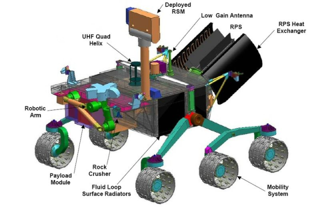
I still read everything I can find about space. Recently, I was reading about Mars Science Laboratory (MSL) and noticed that it has a Radioisotope Thermoelectric Generator (RTG) for a power source. Figure 1 shows an artist's rendering of the MSL with two RTGs, which NASA refers to as the Radioisotope Power System (RPS).

Figure 1: Mars Science Laboratory Rover with Radioisotope Power System (aka RTG).

Figure 1: Mars Science Laboratory Rover with Radioisotope Power System (aka RTG-based Power System).

MSL's use of an RTG got me thinking about a physicist I sat next to on a flight years ago. He worked for Medtronic and had assisted in the development of a "nuclear battery" for use in a pacemaker. It was on that flight that I learned a little bit about RTGs. Let's see if we can use a bit of math to understand how an RTG works and how it is used on the MSL mission. As usual, I will be using Mathcad for the heavy lifting.

Background

Referencing the Wikipedia, lets start with a definition of what an RTG is:

A radioisotope thermoelectric generator (RTG, RITEG) is an electrical generator that obtains its power from radioactive decay. In such a device, the heat released by the decay of a suitable radioactive material is converted into electricity by the Seebeck effect using an array of thermocouples.

Figure 1 (Source) shows a photograph of the RTG used on MSL, which is called the Multi-Mission RTG (MMRTG).

Figure 1: Photograph of MSL's MMRTG.

Figure 1: Photograph of MSL's MMRTG.

I saw the following statement in The Atlantic Magazine about the MMRTG:

The 43kg MMRTG is designed to produce 125 watts of electrical power at the start of the mission, falling to about 100W after 14 years. (NASA/Kim Shiflett)

Let's see if we can use this one statement to derive some information about the MSL's RTG.

Analysis

Amount of Power Required

A thermoelectric generator requires heat to produce electricity. Unfortunately, thermoelectric generators are notoriously inefficient. NASA has reported that their efficiency level is about 6.2%. This means that for every 1000 W put in, only ~62 W of electricity comes out. Since this generator is specified to put out 125 W, we need a heat source that produces {{P}_{Total}}=\frac{125 \text{W}}{6.2 \text{ \%}}=2008\text{ W}. The Wikipedia entry for the MMRTG states that it dissipates 2 kW of power, so we appear to have the correct total power figure and efficiency.

Heat Generated by Radioactive Decay

When a plutonium-238 atom decays, it emits an alpha particle with a decay energy of 5.593 Million Electron Volts (MEV). It is this decay energy is the source of heat (i.e. energy) that will be converted to electricity by thermocouples. This heat is enough to cause the Pu-238 to glow (see Figure 2, Source).

Figure 2: A Glowing Pu-238 RTG Element.

Figure 2: A Glowing Pu-238 RTG Element.

Radioactive decay versus time is usually modeled mathematically using the concept of half-life. Equation 1 shows how half-life is used to model decay.

Eq. 1 N(t)={{N}_{0}}\cdot {{\left( \frac{1}{2} \right)}^{\frac{t}{{{t}_{HL}}}}}

where

  • t is time in years.
  • tHL is the half life of Pu-238 (87.74 years).
  • N is the number of atoms in a sample of radioactive material.
  • N0 is the number of atoms in a sample of radioactive material at t=0.

To compute the power radiated by a sample of Pu-238, we need to determine the number of decays that occur per second. We can compute the number of decays per second by differentiating Equation 1, which I show in Equation 2.

Eq. 2 \frac{dN\left( t \right)}{dt}=N(t)\cdot \frac{\ln \left( \frac{1}{2} \right)}{{{t}_{HL}}}

Let's say we want to compute the amount of heat generated by a gram of Pu-238. We need to determine the number of Pu-238 atoms in a one gram sample and apply Equation 2, which tells us that Pu-238 generates 0.568 W/gm of heat. Figure 4 illustrates this calculation. We can use this number to estimate the amount of Pu-238 that we will need to generate 2 kW of thermal power.

Figure 4: Calculation of Heat Generated Per gm of Pu-238.

Figure 4: Calculation of Heat Generated Per gm of Pu-238.

Amount of Pu-238 Required

Since we know that we require 2 kW of thermal power and that Pu-238 generates 0.568 W/gm, we see that we need {{M}_{\text{Pu238}}}=\frac{2000\text{ W}}{\frac{0.568\text{ W}}{\text{gm}}}=3.5\text{ kg }. This agrees with the value 3.5 kg stated in this presentation from the Department of Energy, so I think we understand how much Pu-238 is required.

Degradation of Performance Over Time

The quote from The Atlantic Magazine states that the electrical power available from the MMRTG drops to 100 W after 14 years. Let's assume that we have a fixed percentage of degradation year over year, which is similar to a compound interest problem. We can determine the percentage decline per year as shown in Equation 3.

Eq. 3 125\cdot {{\left( 1-x \right)}^{14}}=100\Rightarrow x=1.58\%

So the output power is declining by 1.58% every year.

The amount of heat available from a radioactive source degrades every year because the amount of radioactive material reduces every year because of decay. We can compute this decline in thermal power as shown in Equation 4.

Eq. 4 \frac{dN\left( t \right)}{dt}=N(t)\cdot \frac{\ln \left( \frac{1}{2} \right)}{{{t}_{HL}}}
\therefore \frac{\frac{dN\left( t \right)}{dt}}{N\left( t \right)}=\frac{\ln \left( \frac{1}{2} \right)}{{{t}_{HL}}}=-0.79\%

So thermal power declines by 0.79% every year, which is about half of the electrical power drop reported by NASA. However, the thermocouples also degrade in performance every year. So the 1.58% degradation rate is composed of two parts: (1) the reduction in available thermal power due to radioactive decay, and (2) the reduction in thermocouple conversion efficiency over time.

It turns out that there is data from Voyager on RTG power reduction. Over a 33 year period, Voyager has seen its available electrical power decline to 67% of its initial value, though its available thermal power has only declined by 83.4%. This means that Voyager has seen a decline in electrical power generation of 1.7% per year while its thermal power has degraded by 0.79% per year. So that 1.6% degradation expected for the MMRTG by NASA seems reasonable.

Conclusion

I was able to calculate some important characteristics of NASA's power system for the Mars Science Laboratory. I could see problems like this being good ones for calculus students to sharpen their skills on.

There are folks looking at how to improve the efficiency of nuclear batteries (example).

Save

Posted in Batteries, Electronics | 14 Comments

Worked PageRank Example

Introduction

One of my sons asked me if I could work through a PageRank calculation example a couple of different ways (algebraic and iterative). It was an interesting exercise and I thought it would be worth documenting here. I used Mathcad for both my algebraic and iterative solutions.

Wikipedia has an excellent definition of the PageRank algorithm, which I will quote here.

PageRank is a link analysis algorithm, named after Larry Page[1] and used by the Google Internet search engine, that assigns a numerical weighting to each element of a hyperlinked set of documents, such as the World Wide Web, with the purpose of "measuring" its relative importance within the set.

Businesses and individuals who want their site to rank more highly in Google's search results could look at the services of a Digital Marketing Company to help boost their position.
PageRank is computed using a relatively simple function (see Equation 1), but a number of web-based examples treat the weighting of inbound links from sites external to a particular group of pages as a special case. I did not see any explicit calculation examples, so I thought I would include this calculation here. You'll more than definitely want to take this calculation into consideration if you're wanting to learn to how to build a website as well as wishing to attract traffic to your new site. Speaking of which, are you in the process of designing a new website? Whether you are a business or a blogger, running a website ensures that people that are interested in your products or services can learn about them with ease. So, have a web designing agency like The Web Designer Cardiff (click here) to have one made for you professionally. Furthermore, thanks to the advent of website building tools, creating a website has never been more accessible. For a summary of some of the most widely used website builders, head to this makeawebsitehub guide.

Background

PageRank views the web as graph, with inbound links being viewed as measure of the significance of a web page. Equation 1 shows the PageRank equation. Note that this equation can be solved several different ways. One approach involves eigenvalues, which my son does not know about yet. The equation can be solved algebraically or iteratively. I will use both approaches for this example.

Eq. 1 PR\left( {{p}_{i}} \right)=\frac{1-d}{N}+d\cdot \sum\limits_{p\in M\left( {{p}_{i}} \right)}{\frac{PR\left( {{p}_{j}} \right)}{L\left( {{p}_{j}} \right)}}

where

  • N is the number of pages.
  • d is called the damping factor and it is an arbitary weighting factor.
  • PR(pi is the PageRank of page pi.
  • L(pi) is the number of outbound links from page pi.
  • M(pi) is the set of links to page pi.

Equation 2 shows a matrix form of Equation 1. The matrix form is most likely the form used "out in the wild."

Eq. 2 \mathbf{R}(t+1)=d\cdot \mathcal{M}\cdot \mathbf{R}(t)+\frac{1-d}{N}\cdot \mathbf{1}\text{ }~

where

  • R is the PageRank vector.
  • 1 is a column vector with all elements equal to 1.
  • t is a discrete time variable (really a sequence number).

Note that many examples of PageRank are computed using a variant of Equations 1 and 2 that multiplies the PageRank value by the number of pages (N ·PageRank). Equation 3 illustrates Equation 2 modified with the substitution \mathbf{{R}'}=N\cdot \mathbf{R}. Equation 1 can be modified similarly. This is the equation that Ian used for his examples. Since I am going to duplicate his results, I will multiply my results by N.

Eq. 3 N\cdot \mathbf{R}(t+1)=N\cdot d\cdot \mathcal{M}\cdot \mathbf{R}(t)+N\cdot \frac{1-d}{N}\cdot \mathbf{1}
\left( N\cdot \mathbf{R}(t+1) \right)=d\cdot \mathcal{M}\cdot \left( N\cdot \mathbf{R}(t) \right)+\left( 1-d \right)\cdot \mathbf{1}
\therefore \quad \mathbf{{R}'}(t+1)=d\cdot {\mathcal{M}}'\cdot \mathbf{{R}'}(t)+\left( 1-d \right)\cdot \mathbf{1},\text{ where }\mathbf{{R}'}=N\cdot \mathbf{R}

There has been quite a bit written about the nuances of this equation because of its importance in determining a web page's position in a list of search results. I am not concerned about those details here. I am focused here on the calculation of the PageRank for a specific set of pages.

Analysis

Example

My son was using Ian Roger's excellent site for learning about the details of PageRank. The question he had is on Example 10, which assigns a PageRank of 1 to an external page. Figure 1 shows the Example 10's web page configuration. Ian's PageRank results are shown in the boxes, which represent web pages. I want to show the details on obtaining Ian's results as an illustration of how to handle an external link from a page with a defined PageRank.

Figure 1: PageRank Example from Ian Roger's Website.

Figure 1: PageRank Example from Ian Roger's Website.


I have added the letters A-F to Figure 1, which constitute the variable names I will use in my solutions.

Algebraic Solution

When Ian uses a link from an external site, he sets the PageRank value to 1. Here is his rationale.

We'll assume there's an external site that has lots of pages and links with the result that one of the pages has the average PR of 1.0.

Algebraically, this is easy to handle. Figure 2 shows my solution implemented in Mathcad.

Figure 2: Algebraic Solution for Example 10.

Figure 2: Algebraic Solution for Example 10.

Iterative Solution

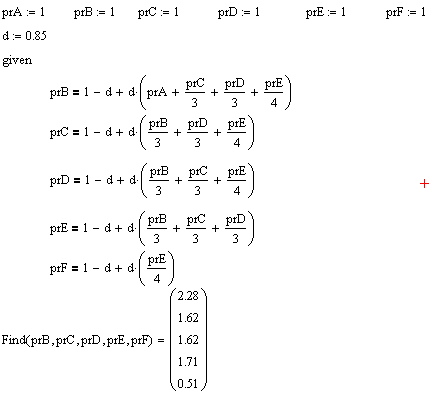
Figure 3 shows how I setup my iterative solution. To force page A to have a PageRank of 1, I needed to remove page A from the R vector and M matrix, but add it back in so that page A's contribution can be included. Again, it is a slight modification of Equation 3 so that I can force page A to have a PageRank of 1.

Figure 3: Setup for My Iterative Solution of Equation 2.

Figure 3: Setup for My Iterative Solution of Equation 2.


Figure 4 shows my iteration stage. Note that I was lazy and simply let it iterate a 1001 times. I could have made this much more efficient by simply monitoring the convergence, but that would have taken a bit more time.
Figure 4: Iterative Solution of Equation 2.

Figure 4: Iterative Solution of Equation 2.

Conclusion

I obtained the same results as Ian using two different approaches -- algebraic and iterative. This example was different than most in that a particular web page was forced to a particular PageRank. I hope that I answered my son's question.

Posted in software | Tagged , | Comments Off on Worked PageRank Example

Bolide Meteor Sighting

I saw a bolide meteor while driving out to Montana last week. For those who are not familiar with bolide meteors, the Wikipedia has a nice description.

The word bolide comes from the Greek βολίς (bolis) [2] which can mean a missile or to flash. The IAU has no official definition of "bolide", and generally considers the term synonymous with "fireball". The term generally applies to fireballs reaching magnitude −14 or brighter.[12] Astronomers tend to use "bolide" to identify an exceptionally bright fireball, particularly one that explodes (sometimes called a detonating fireball). It may also be used to mean a fireball which creates audible sounds.

I have seen two bolide meteors in my life. I saw my first one while walking home from Catholic education one evening during 8th grade. It was very bright and lasted only a short period of time. About 30 seconds after it vanished, I heard a rumble. Next day, the local newspaper reported that a meteor had been spotted and fragments had been picked up on the ground.

Last week, I was driving late in the evening when I saw a bright white streak come across the sky that appeared to drop a yellow and then a green fragment. I have watched meteors my whole life and this was the first time that I saw colors. I did not know that others have seen colors until I saw this article. This was pretty cool!

Posted in Astronomy | Comments Off on Bolide Meteor Sighting